PRE-RELEASE
Instrument Panel Tie Bar Replacement
| Instrument Panel Tie Bar Replacement |
| Removal Procedure |
| 1. |
Recover the air conditioning refrigerant. Refer to
Refrigerant Recovery and Recharging (Belt Driven Compressor)
|
|
| 2. |
Drain the engine cooling system. Refer to
Cooling System Draining and Filling (GE 47716)
Cooling System Draining and Filling (Static Fill LAU)
Cooling System Draining and Filling (Static Fill LF1)
|
|
| 3. |
Remove the heater inlet hose from the heater core tube. Refer to
Heater Inlet Hose Replacement (LF1)
Heater Inlet Hose Replacement (LAU)
|
|
| 4. |
Remove the heater outlet hose from the heater core tube. Refer to
Heater Outlet Hose Replacement (LF1)
Heater Outlet Hose Replacement (LAU)
|
|
| 5. |
Remove the evaporator hose assembly from the thermal expansion valve. Refer to
Air Conditioning Condenser and Air Conditioning Evaporator Tube Replacement
|
|
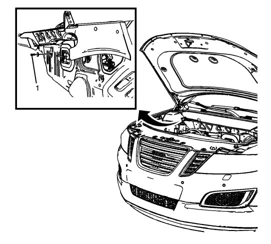
| 6. |
Within the engine compartment area remove the fastener (1) securing the HVAC module assembly to the vehicle body.
|
|
| 7. |
Remove the instrument panel assembly from the vehicle. Refer to
Instrument Panel Assembly Removal
|
|
| 8. |
Remove the communication interface module and bracket assembly. Refer to
Communication Interface Module Bracket Replacement
|
|
| 9. |
Remove the body control module and bracket. Refer to
Body Control Module Bracket Replacement
|
|
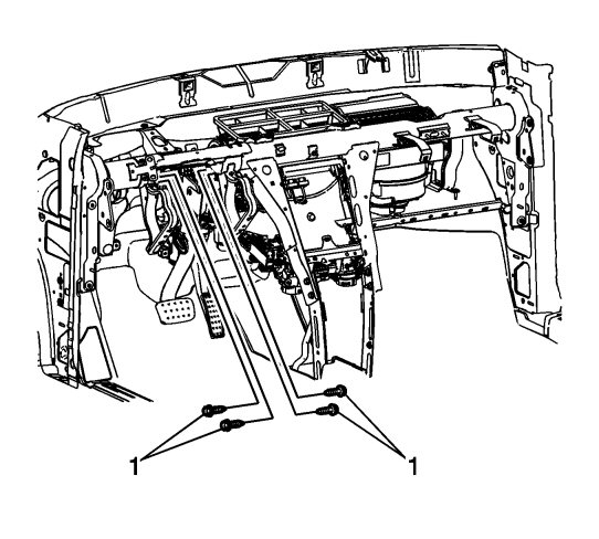
| 10. |
Remove the four bolts (1) securing the brake pedal assembly to the instrument panel tie bar.
|
|
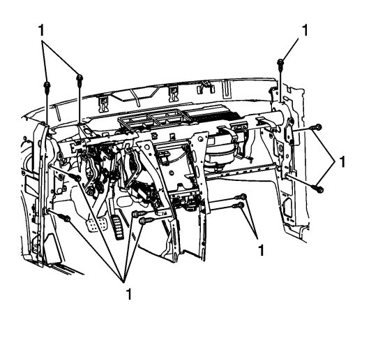
| 11. |
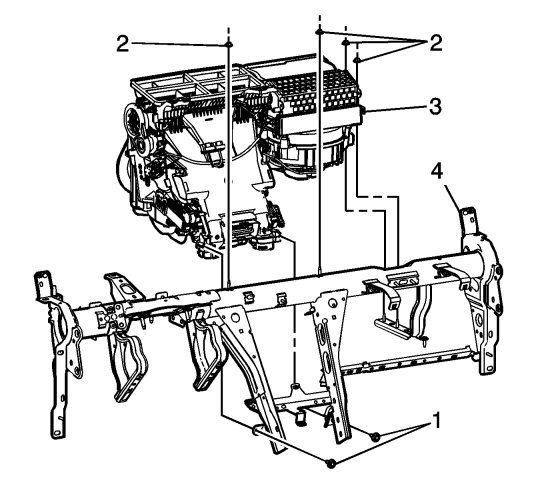
Remove the eleven bolts (1) securing the instrument panel tie bar to the vehicle.
|
|
| 12. |
Note location and routing of the instrument panel wiring harness around the instrument panel tie bar prior to removal to ensure proper reinstallation.
|
|
| 13. |
Disconnect any retainers securing the instrument panel wiring harness to the tie bar assembly and position the wiring harness out of the way.
|
|
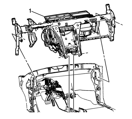
| 14. |
With the aid of an assistant remove the instrument panel tie bar and HVAC module assembly as a unit (1) from the vehicle.
|
|
| 15. |
Remove the two bolts (1) securing the HVAC module (3) to the instrument panel tie bar assembly (4).
|
|
| 16. |
Remove the four nuts (2) securing the HVAC module (3) to the instrument panel tie bar assembly (4).
|
|
| 17. |
Separate the HVAC module (3) from the instrument panel tie bar assembly (4).
|
|
| Installation Procedure |
| 1. |
When replacing the instrument panel tie bar assembly, transfer all necessary components.
|
|
| 2. |
Align the HVAC module (3) to the instrument panel tie bar assembly (4).
|
|
| 3. |
Loosely install the four nuts (2) securing the HVAC module (3) to the instrument panel tie bar assembly (4).
|
|
| 4. |
Loosely install the two bolts (1) securing the HVAC module (3) to the instrument panel tie bar assembly (4).
|
|
| 5. |
Refer to
Fastener Caution
Tighten the four nuts and the two bolts securing the HVAC module (3) to the instrument panel tie bar assembly (4) to 6 Nm(53 lb in) . |
|
| 6. |
With the aid of an assistant position the instrument panel tie bar and HVAC module assembly as a unit (1) into the vehicle.
|
|
| 7. |
Reposition the wiring harness as was noted in the removal procedure and re-secure any retainers removed in order to secure the instrument panel wiring harness to the tie bar assembly.
|
|
| 8. |
Loosely install the eleven bolts (1) securing the instrument panel tie bar to the vehicle.
|
|
| 9. |
Once all eleven bolts (1) are loosely installed, tighten the bolts to
22 Nm(16 lb ft)
.
|
|
| 10. |
Loosely install the four bolts (1) securing the brake pedal assembly to the instrument panel tie bar.
|
|
| 11. |
Once all four bolts (1) are loosely installed, tighten the bolts to
21 Nm(15 lb ft)
|
|
| 12. |
Install the body control module and bracket. Refer to
Body Control Module Bracket Replacement
|
|
| 13. |
Install the communication interface module and bracket assembly. Refer to
Communication Interface Module Bracket Replacement
|
|
| 14. |
Install the instrument panel assembly from the vehicle. Refer to
Instrument Panel Assembly Removal
|
|
| 15. |
Within the engine compartment area install the fastener (1) securing the HVAC module assembly to the vehicle body, tighten the fastener (1) to
1.4 Nm(12 lb in)
.
|
|
| 16. |
Install the evaporator hose assembly to the thermal expansion valve. Refer to
Air Conditioning Condenser and Air Conditioning Evaporator Tube Replacement
|
|
| 17. |
Install the heater outlet hose to the heater core tube. Refer to
Heater Outlet Hose Replacement (LF1)
Heater Outlet Hose Replacement (LAU)
|
|
| 18. |
Install the heater inlet hose to the heater core tube. Refer to
Heater Inlet Hose Replacement (LF1)
Heater Inlet Hose Replacement (LAU)
|
|
| 19. |
Refill the engine cooling system. Refer to
Cooling System Draining and Filling (GE 47716)
Cooling System Draining and Filling (Static Fill LAU)
Cooling System Draining and Filling (Static Fill LF1)
|
|
| 20. |
Recharge the air conditioning refrigerant system. Refer to
Refrigerant Recovery and Recharging (Belt Driven Compressor)
|
|
