PRE-RELEASE
To fit
| To fit |
| 1. |
Lubricate the primary shaft splines, see
Summary of lubricants and sealants
.
|
|
| 2. |
If the slave cylinder is new or has been emptied of brake fluid the system must be bled, See
Bleeding of the slave cylinder
.
|
|
| 3. |
Fit
83 95 162 Protective collar, drive shafts
in the right-hand shaft seal in the transmission to protect the seal when the transmission is being fitted.
|
||||||||||
| 4. |
Raise the car.
|
|
| 5. |
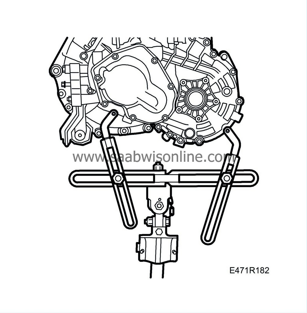
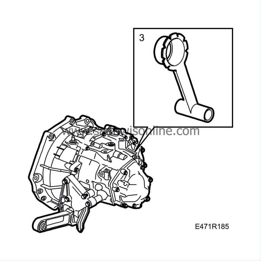
Connect the lifting tool
87 92 608 Holder for pillar jack
.
|
|
| 6. |
Adjust the lifting tool so its centre is aligned with the centre of the gearbox and the mating face.
|
|
| 7. |
Fit the gearbox with lifting tool onto a pillar jack.
|
||||||||||
| 8. |
Push in the rest of the gearbox. Turn the engine shaft, if needed, so that the gearbox can be fitted.
|
|
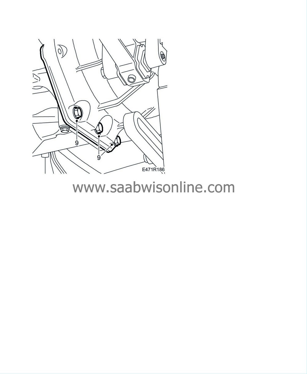
| 10. |
Tighten the lower screws between the engine and gearbox.
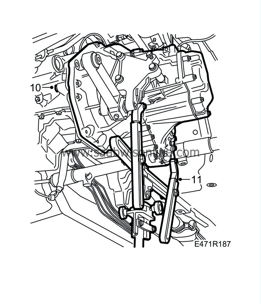
Tightening torque 70 Nm (50 lbf ft) |
|
| 11. |
Remove the lifting tool from the gearbox and remove the jack.
Refit the gearbox bolts. Tightening torque 24 Nm (18 lbf ft) |
|
| 12. |
Attach the ground straps to the grounding point and the gearbox.
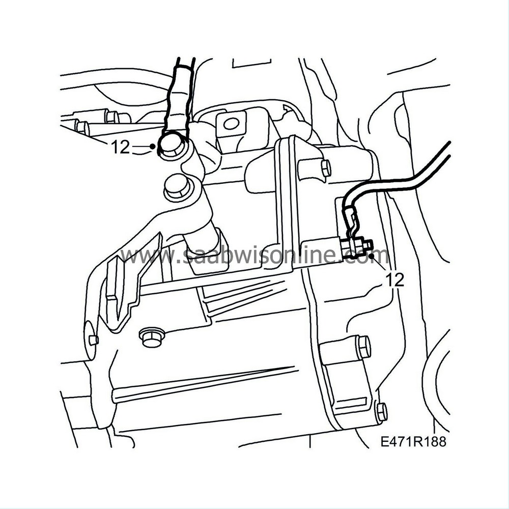
|
|
| 13. |
Fit
83 95 162 Protective collar, drive shafts
into the left-hand drive shaft seal.
|
|
| 14. |
Make sure that the driver is clean and fit it into the tool.
|
||||||||||
| 15. |
Push in the rest of the shaft until the circlip snaps into place.
|
|
| 16. |
Lower the car to the floor.
|
|
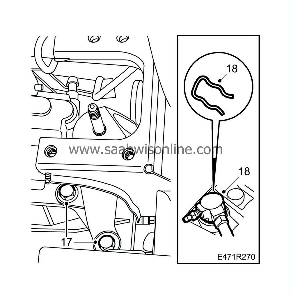
| 17. |
Fit the gearbox mounting.
Tightening torque 40 Nm (30 lbf ft) |
|
| 18. |
Connect the clutch delivery pipe to the gearbox and fit the locking clip, check that the pipe is firmly fixed at the mounting point on the vehicle body.
|
|
| 19. |
Raise the power train.
|
|||||||
| 20. |
Fasten the left-hand engine pad to the body and the gearbox after having first positioned all the nuts and bolts.
Tightening torques, Engine pad - gearbox 85 Nm (62 lbf ft) Engine pad - body 60 Nm (45 lbf ft) |
|
| 21. |
Attach the stay to the gearbox and the engine pad. Tighten the upper gearbox bolts.
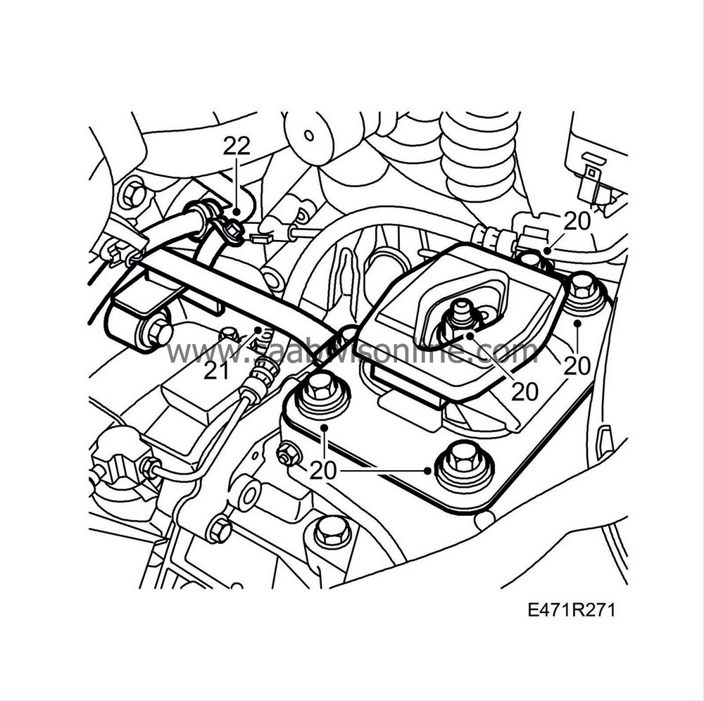
Tightening torque, gearbox 70 Nm (50 lbf ft) Tightening torque, stay to engine pad 63 Nm (46 lbf ft) |
|
| 22. |
Fit the starter motor cable clamp.
|
|
| 23. |
Fill the gearbox with oil up to the correct level. Use the fitting tool
87 92 590 Tool, oil level plug
. Tighten the level plug, drain plug, and filler plug.
Tightening torque 50 Nm (37 lbf ft) 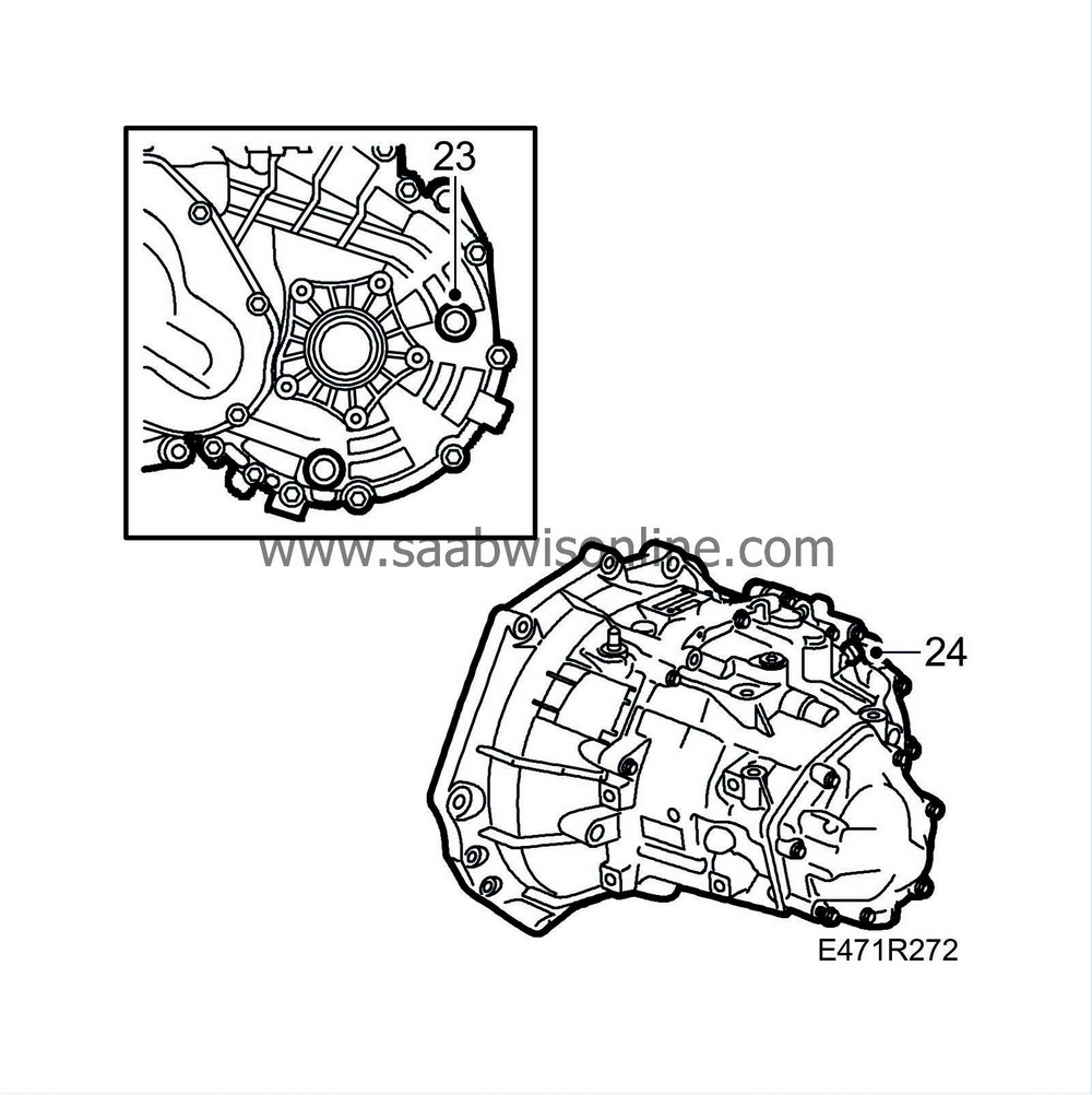
|
|
| 24. |
Connect the lead to the reversing-light switch.
|
|
| 25. |
Check that the journals for the radiator assembly are correctly fixated in the radiator member.
|
|
| 26. |
Hang down the oil cooler.
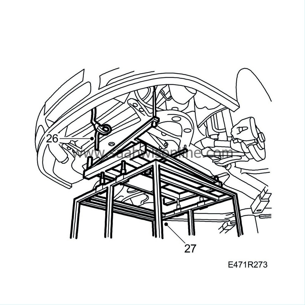
|
|
| 27. |
Raise the car and position the lifting trolley with the subframe under the car.
|
|
| 28. |
Carefully raise the subframe.
|
|||||||||||||||||||
| 29. |
Tighten the two power steering delivery pipe fixings before the subframe is fully raised.
|
|
| 30. |
Guide the radiator assembly journals into the subframe.
|
|
| 31. |
Guide the A/C pipes into their brackets on the subframe.
|
|
| 32. |
Adjust the position of the subframe so that the bolt holes align with those on the body. On the lifting trolley there are 2 guide pins, front left and right back, which guide the subframe into the correct position.
|
|
| 33. |
Fit the bolts and rear support plate which secure the subframe.
|
|
| 34. |
Roll the lifting trolley out of the way.
|
|
| 35. |
Tighten the screws for the subframe.
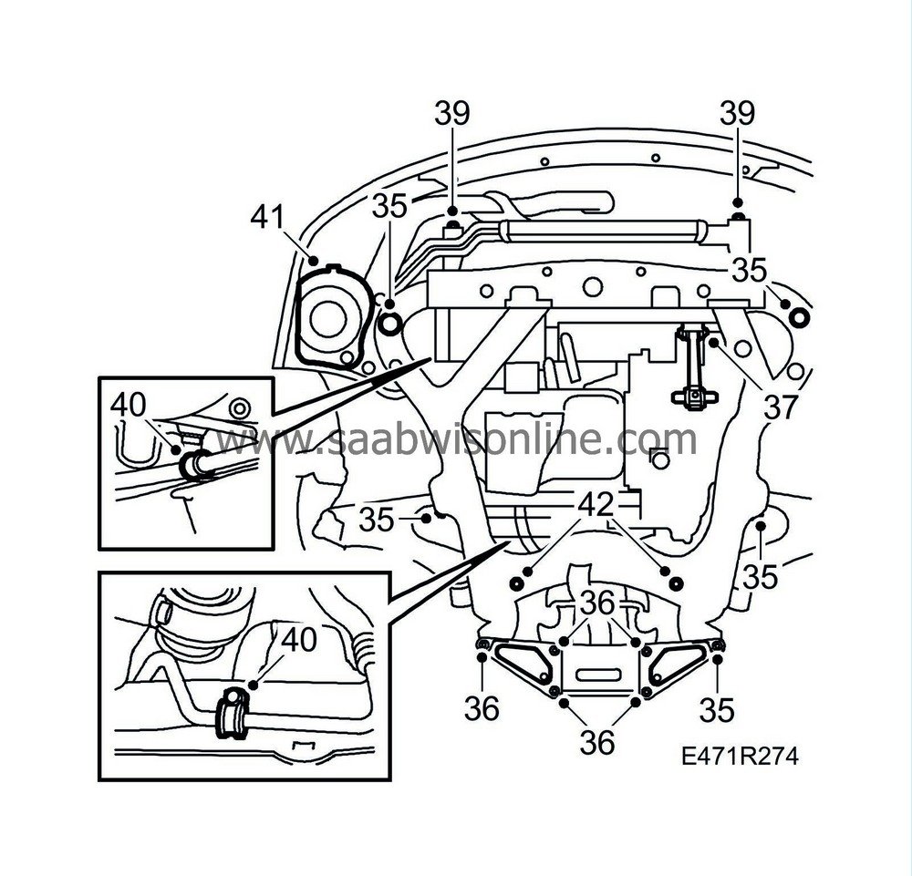
Tightening torque 100 Nm + 45° (74 lbf ft + 45°) |
|
| 36. |
Tighten the screws for the support plate.
Tightening torque 60 Nm (44 lbf ft) |
|
| 37. |
Fit and tighten the bolt that secures the torque arm to the subframe.
Tightening torque 90 Nm + 90° (66 lbf ft + 90°) |
|
| 38. |
Remove the strap holding up the radiator core.
|
|
| 39. |
Fit the engine oil cooler.
|
|
| 40. |
Tighten the 2 rear clamps holding the power steering delivery pipe at the connection to the subframe. Tighten the nut which fastens the oil cooler cooling pipe.
|
|
| 41. |
Tighten down the air filter housing.
|
|
| 42. |
Tighten down the steering gear.
Tightening torque 90 Nm (66 lbf ft) |
|
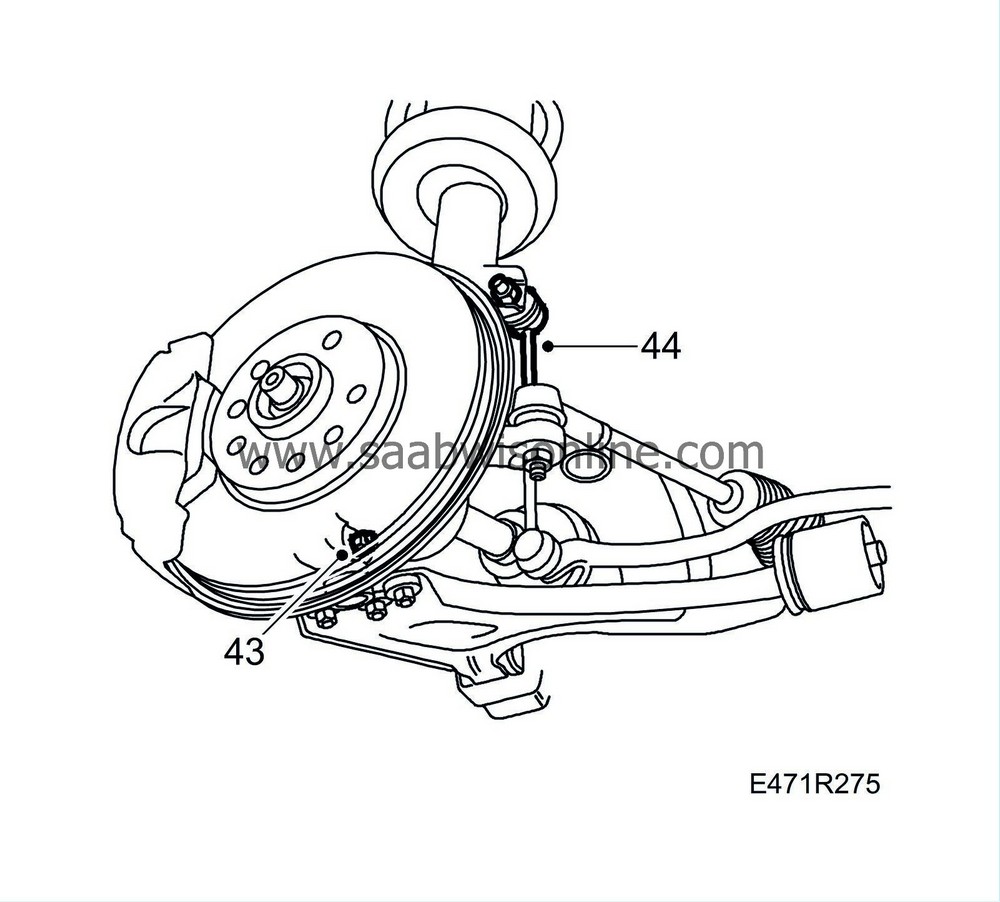
| 44. |
Fit the anti-roll bar supports. Hold with a thin, open 17 mm wrench or hold the hexagonal pin with a socket.
Tightening torque 84 Nm (62 lbf ft) Tightening torque, nut with steel lock: 95 Nm (66 lbf ft)
|
|||||||
| 45. |
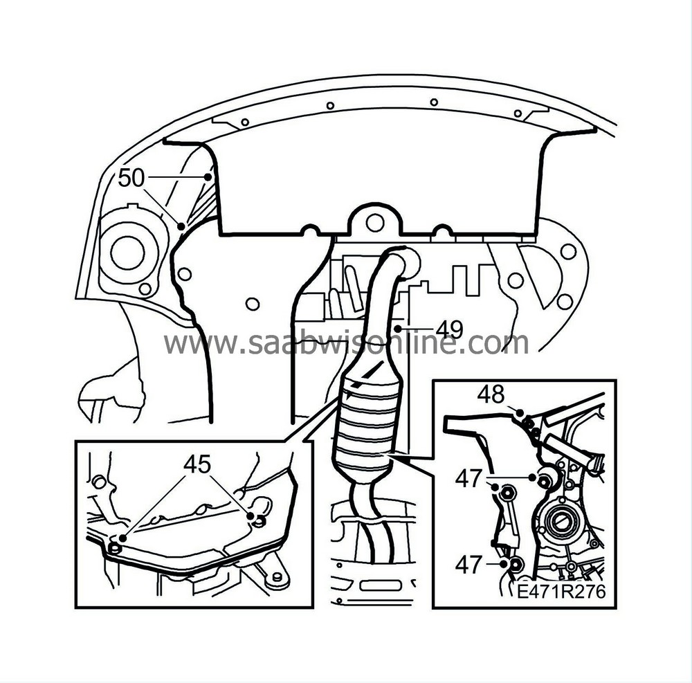
Fit the protection cover between the engine and the gearbox (not B235R).
|
|
| 46. |
Mount the rear engine pad, with bolts inserted, onto the subframe and loosely screw in the front screws.
|
|
| 47. |
Fit the rear engine mount, the gear change linkage is fitted at the same time.
Tightening torque 70 Nm (50 lbf ft) |
|
| 48. |
Fit and tighten the stay between the engine mount and the engine.
Tightening torque 22 Nm (16 lbf ft) |
|
| 49. |
Fit the front exhaust pipe as follows:
|
|
| • |
Fasten the flange against the turbo.
Tightening torque 25 Nm (18 lbf ft) |
| • |
Fit and tighten the stay to the engine.
Tightening torque 22 Nm (16 lbf ft) |
| • |
Fit the locking clip on the rubber mounting.
|
| • |
See also
Forward exhaust system with catalytic converter, 4 cyl. B205E
or
Forward exhaust system with catalytic converters, B235E/R
.
|
| 50. |
Fit the headlight position sensor (if fitted). Fit the shields and the pulley drive system splash guard.
|
|
| 51. |
Lower the vehicle and remove the lifting beam.
|
|
| 52. |
Shake the power train in order to avoid stresses in the engine pads. Tighten the rear engine pad bolts, working from the engine compartment side. Begin with the rearmost bolt.
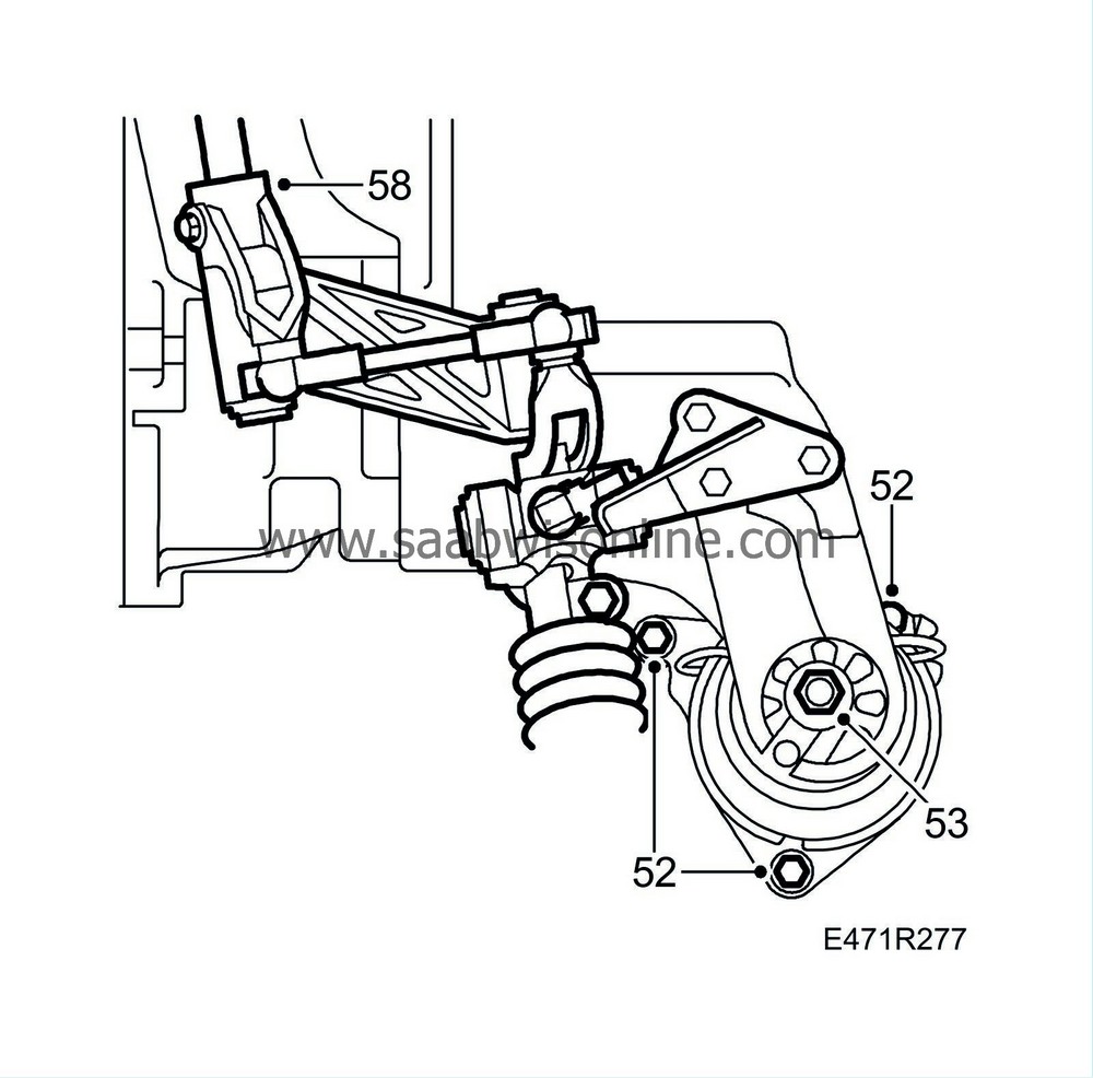
Tightening torque 24 Nm (18 lbf ft) |
|
| 53. |
Tighten the rear engine pad nut.
Tightening torque 45 Nm (33 lbf ft) |
|
| 54. |
Raise the car.
|
|
| 55. |
Slacken the bolt securing the front torque arm to the gearbox and centre the rubber pad in the arm. Tighten the bolt.
Tightening torque 47 Nm (34 lbf ft) |
|
| 56. |
Lower the car to the floor.
|
|
| 57. |
Remove the brake cramp from the clutch pedal. Connect a tube to the bleed nipple, slacken the nipple and let some brake fluid run out. Tighten the nipple and test the clutch, if it does not function bleed as described in
Bleeding the brake system
.
Check that there are no system leaks. |
|
| 58. |
Fit the selector linkage to the gearbox and tighten.
Tightening torque 24 Nm (17 lbf ft) |
|
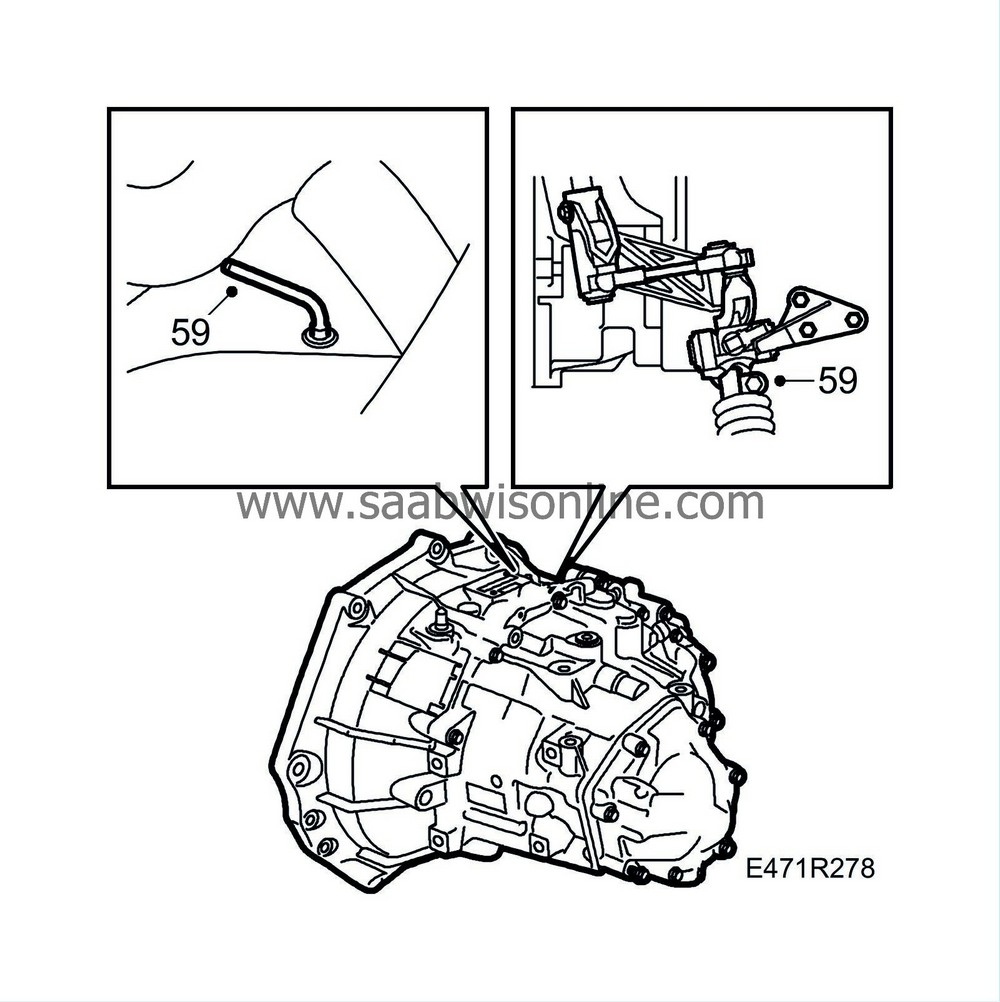
| 59. |
Remove the locking pin
87 92 335 Locking pin
from the gear lever housing and attach the gear change linkage to the selector rod.
|
|
| 60. |
Select 4th gear and fit the
87 92 632 Locking pin
. Tighten the clamp on the gear change linkage.
Tightening torque 22 Nm (16 lbf ft) |
|
| 61. |
Remove the locking pins, check the function of all gear positions and that the ignition key can be removed. Fit the plastic plug into the gearbox. Replace the gaiter.
|
|
| 62. |
Connect the oxygen sensors
|
|
| 63. |
Fit the main fuse box.
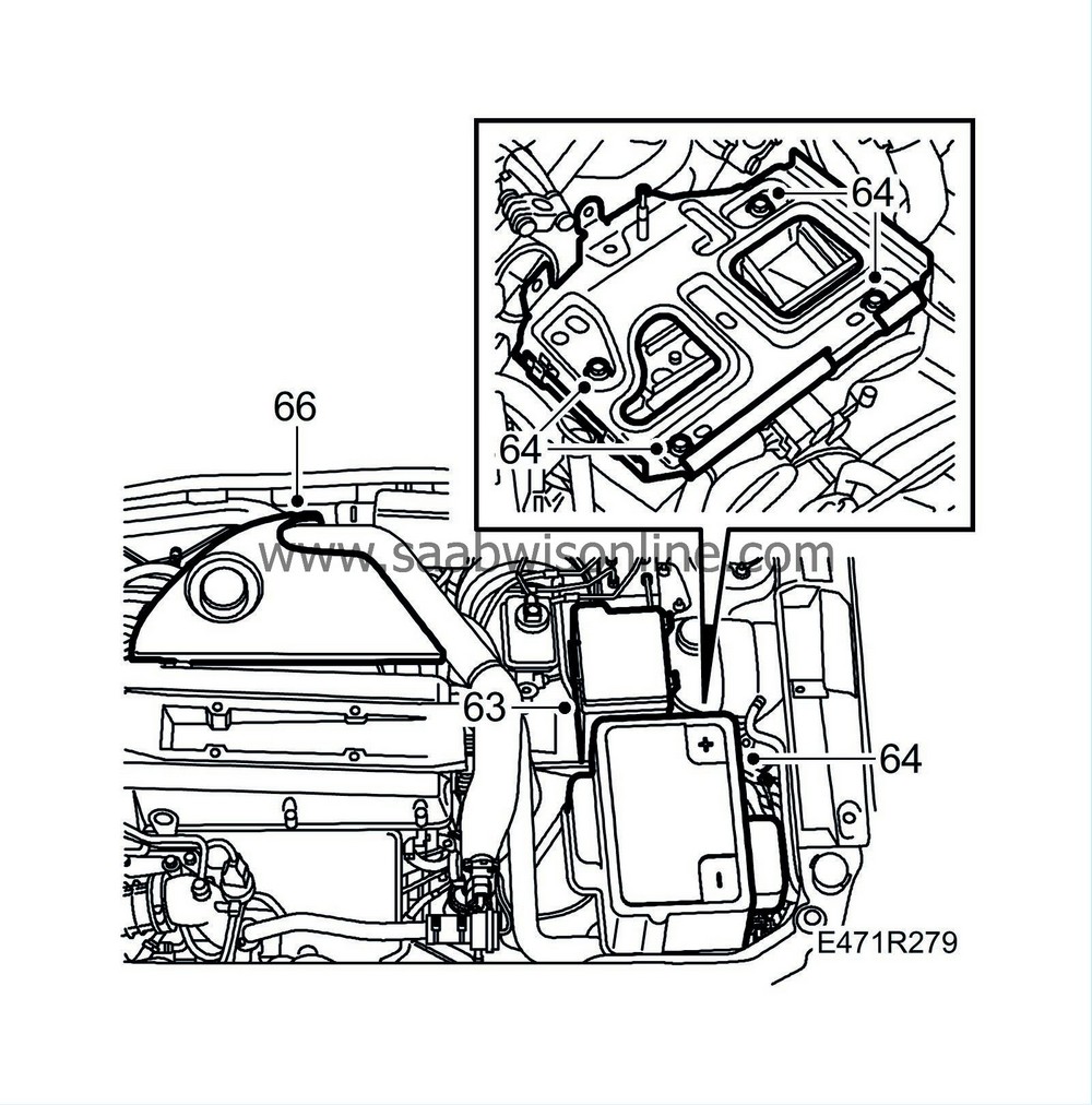
|
|
| 64. |
Fit the battery tray. Fit and connect the battery and put on the plastic cover.
|
|
| 65. |
Fit the front wheels, the wheels must hang freely. See
Wheels
Tightening torque 110 Nm (80 lbf ft) |
|
| 66. |
Fit the throttle housing cover.
|
|
| 67. |
Test drive the car. Check the position of the steering wheel when driving straight ahead on a level road. Adjust if needed.
|
|
| 68. |
Set the correct time and radio code.
|
|


 Warning

