Valve gear
| Valve gear |
| Important | ||
|
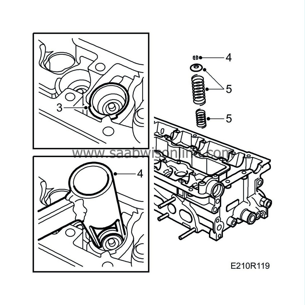
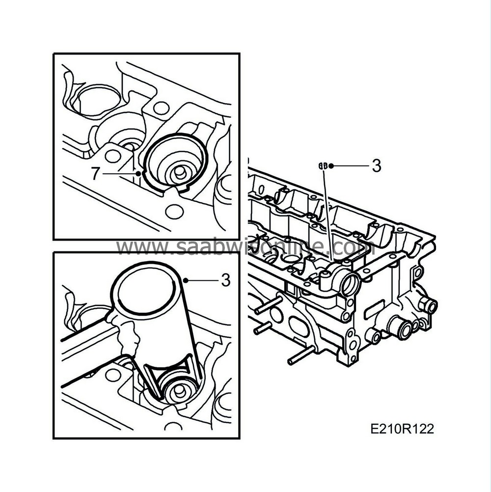
The cylindrical surfaces surrounding the valve springs are sliding surfaces for the tappets. These surfaces must not be scored. Therefore, protect the tappet guides with Protective collar, tappets 83 93 746. |
||
| 1. |
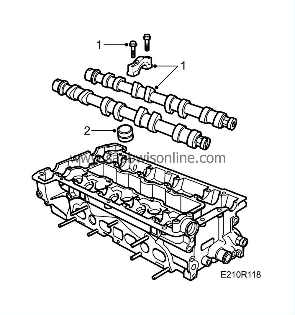
Remove the camshaft bearing caps, it is important to finish removal of the bearing cap where the tappets are under load, and lift out the camshafts.
|
|
| 2. |
Remove the tappets and keep them in the
Valve stand
83 93 787.
|
|
| 3. |
Fit the
Protective collars
83 93 746 .
|
|
| 4. |
Use
Valve spring compressor
83 93 761 and
Valve spring depressor
83 93 779 to remove the collets.
|
|
| 5. |
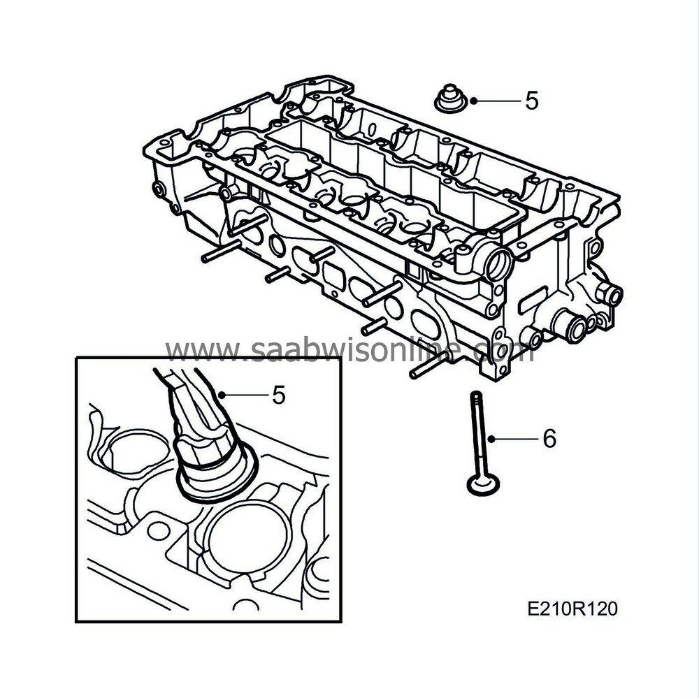
Lift out the valve discs and valve springs. Lift out the washer with guide seals with
Tong for removing valve guide seals
83 94 157.
|
|
| 6. |
Remove the valves. Keep them in
Valve stand
83 93 787.
|
|
| Fitting the valve gear |
| Important | ||
|
Defective valve stem seals must be replaced. The sealing surfaces and bearings must be lubricated with oil before the valves are fitted. Make sure that the cylinder head rests on blocks to prevent damage to the valves (bent valve stems) when the camshafts are tightened down. |
||
| 1. |
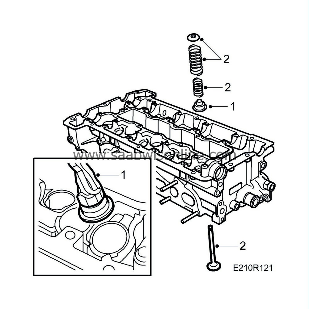
Fit the washer with valve stem seal using
Tong for removing valve guide seal
83 94 157.
|
|
| 2. |
Fit the valves and springs.
|
|
| 3. |
Use valve spring compressor 83 93 761 and
Valve spring depressor
83 93 779 to refit the collets.
|
|
| 4. |
Place
Valve clearance gauge
83 93 753 across two of the camshaft bearing seats with the depth gauge against the end of the valve stem.
|
|
| 5. |
Check that the maximum depth of 20.5 mm reaches down to the end of the valve stem (valve clearance gauge does not bottom in the bearing seat closest to the depth gauge), see
Checking valve clearances
.
|
|
| 6. |
Then check that the minimum gauge depth of 19.5 mm does not reach down to the end of the valve stem. The correct valve clearance is between the minimum and maximum gauge depths. If the clearance is less than the minimum, the valve stem must be shortened and if it is greater than the maximum the valve seat must be reground.
|
|
| 7. |
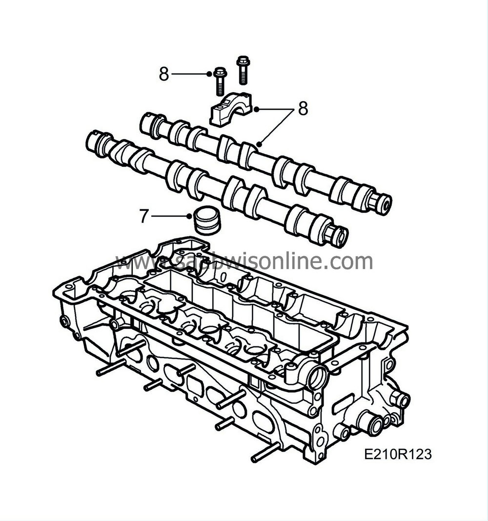
Remove the protective sleeves and fit the valve tappets.
|
|
| 8. |
Fit the camshafts and bearing caps, starting where the cams point downwards and press on the tappets. Bearing caps marked 1-5 for the inlet side, 6-10 for the exhaust side.
Tightening torque 15 Nm (11 lbf ft).
|
||||||||||
| 9. |
Line up the marks on the camshafts with their timing marks.
|
|

