Piston, Connecting Rod, and Bearing Cleaning and Inspection (LDK, LHU)
|
|
Piston, Connecting Rod, and Bearing Cleaning and Inspection (LDK, LHU)
|
|
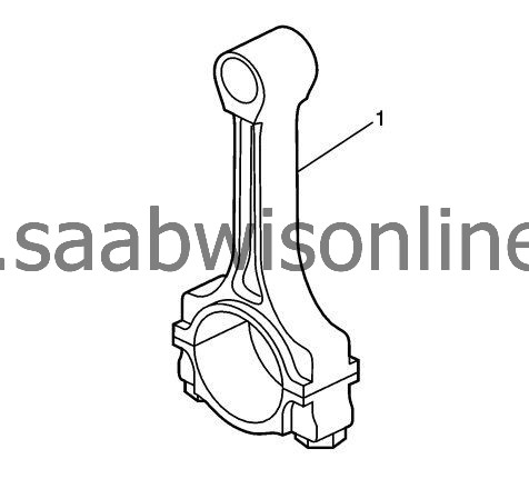
Connecting Rod Measurement
|
|
1.
|
Clean the connecting rods (1) in solvent and dry with compressed air.
|
|
2.
|
Inspect the connecting rods for the following conditions:
|
|
|
•
|
Signs of being twisted, bent, nicked, or cracked
|
|
|
•
|
Scratches or abrasion on the rod bearing seating surface
|
|
3.
|
If the connecting rod bores contain minor scratches or abrasions, clean the bores in a circular direction with fine emery cloth. DO NOT scrape the rod or rod cap.
|
|
4.
|
If the beam of the rod is scratched or has other damage replace the connecting rod.
|
|
5.
|
Measure the piston pin to connecting rod bore using the following procedure:
|
|
|
5.1.
|
Using an outside micrometer, take two measurements of the piston pin in the area of the connecting rod contact.
|
|
|
5.2.
|
Using an inside micrometer, measure the connecting rod piston pin bore.
|
|
|
5.3.
|
Subtract the piston pin diameter from the piston pin bore diameter.
|
|
|
5.4.
|
The clearance should not be more than 0.021 mm (0.0008 in).
|
|
6.
|
If there is excessive clearance, replace the piston pin.
|
|
7.
|
If there is still excessive clearance, replace the connecting rod.
|
|
1.
|
Clean the piston skirts and the pins with a cleaning solvent. DO NOT wire brush any part of the piston.
|
|
2.
|
Clean the piston ring grooves with a groove cleaner. Ensure the oil ring holes and slots are clean.
|
|
3.
|
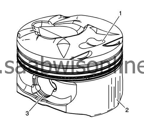
Inspect the pistons for the following conditions:
|
|
|
•
|
Cracked ring lands, skirts, or pin bosses
|
|
|
•
|
Ring grooves for nicks, burrs that may cause binding
|
|
|
•
|
Warped or worn ring lands
|
|
|
•
|
Eroded areas at the top of the piston (1)
|
|
|
•
|
Scuffed or damaged skirts (2)
|
|
|
•
|
Worn piston pin bores (3)
|
|
4.
|
Replace pistons that show any signs or damage or excessive wear.
|
|
5.
|
Measure the piston pin bore to piston pin clearances using the following procedure:
|
|
|
5.1.
|
Piston pin bores and pins must be free of varnish or scuffing.
|
|
|
5.2.
|
Use an outside micrometer to measure the piston pin in the piston contact areas.
|
|
|
5.3.
|
Using an inside micrometer, measure the piston pin bore.
|
|
|
5.4.
|
Subtract the measurement of the piston pin bore from the piston pin. The clearance should be within 0.002-0.012 mm (0.00007-0.00047 in).
|
|
|
5.5.
|
If the clearance is excessive, determine which component is out of specification.
|
|
6.
|
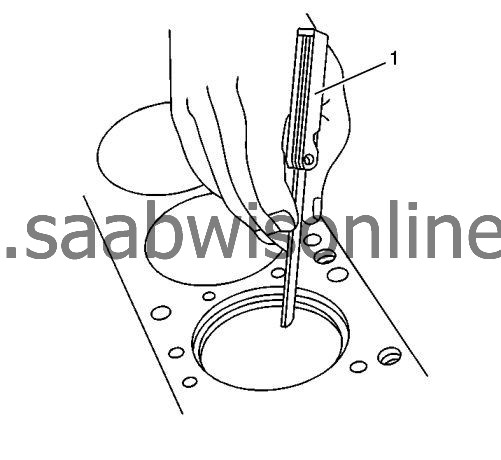
Measure the piston ring end gap using the following procedure:
|
|
|
6.1.
|
Place the piston ring in the area of the bore where the piston ring will travel, approximately 25 mm or 1 inch down from the deck surface. Ensure the ring is square with the cylinder bore by positioning the ring with the piston head.
|
|
|
6.2.
|
Measure the end gap of the piston ring with feeler gauges (1). Compare the measurements with those provided below:
Specification
|
•
|
The top compression ring end gap should be 0.20-0.35 mm (0.0078-0.0138 in).
|
|
•
|
The second compression ring end gap should be 0.35-0.55 mm (0.0137-0.0216 in).
|
|
•
|
The oil ring end gap should be 0.25-0.76 mm (0.0098-0.029 in).
|
|
|
|
0.3.
|
If the clearance exceeds the provided specifications, the piston rings must be replaced.
|
|
|
0.4.
|
Repeat the procedure for all the piston rings.
|
|
1.
|
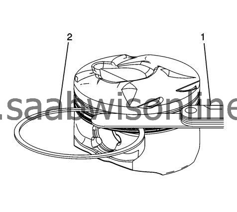
Measure the piston ring side clearance using the following procedure:
|
|
|
1.1.
|
Roll the piston ring (2) entirely around the piston ring groove. If any binding is caused by a distorted piston ring, replace the ring.
|
|
|
1.2.
|
With the piston ring on the piston, use feeler gauges (1) to measure clearance at multiple locations.
|
|
|
1.3.
|
The clearance between the surface of the top piston ring and the ring land should be no greater than 0.055 mm (0.0022 in).
|
|
|
1.4.
|
If the clearance is greater than specifications, replace the piston ring.
|
|
|
1.5.
|
If the new ring does not reduce the top ring side clearance to 0.055 mm (0.0022 in) or less, install a new piston.
|
|
2.
|
The top compression ring may be installed with either side up. There is a locating dimple on the second compression ring near the end for identification of the top side. Install the second compression ring with the dimple facing up.
|
|
3.
|
The clearance between the surface of the second piston ring and the ring land should be no greater than 0.032 mm (0.0012 in).
|
|
4.
|
If the new ring does not reduce the clearance to 0.032 mm (0.0012 in) or less, install a new piston.
|
|
5.
|
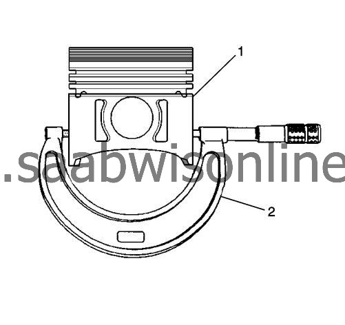
Measure piston width using the following procedure:
|
|
|
5.1.
|
Using an outside micrometer (2), measure the width of the piston (1) 12.5 mm (0.4925 in) above the bottom of the piston skirt at the thrust surface perpendicular to the centerline of the piston pin.
|
|
|
5.2.
|
Compare the measurement of the piston to its original cylinder by subtracting the piston width from the cylinder diameter.
|
|
|
5.3.
|
The proper clearance specification for the piston is 0.010-0.041 mm (0.0006-0.0016 in).
|
|
6.
|
If the clearance obtained through measurement is greater than these specifications and the cylinder bores are within specification, replace the piston.
|
|
1.
|
|
Note
|
|
•
|
Measurements of all components should be taken with the components at normal room temperature.
|
|
•
|
For proper piston fit, the engine block cylinder bores must not have excessive wear or taper.
|
|
•
|
A used piston and pin set may be reinstalled if, after cleaning and inspection, they are within specifications.
|
Inspect the engine block cylinder bore. Refer to
Engine Block Cleaning and Inspection
.
|
|
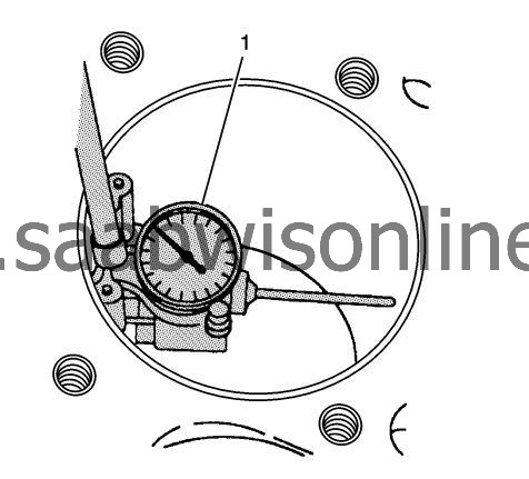
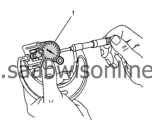
3.
|
Using a bore gauge (1), measure the cylinder bore diameter. Measure at a point 64 mm (2.5 in) from the top of the cylinder bore.
|
|
4.
|
Measure the bore gauge (1) with a micrometer and record the reading.
|
|
5.
|
With a micrometer (2) or caliper at a right angle to the piston, measure the piston (1) 14 mm (0.570 in) from the bottom of the skirt.
|
|
6.
|
Subtract the piston diameter from the cylinder bore diameter in order to determine piston-to-bore clearance.
|
|
8.
|
If the proper clearance cannot be obtained, select another piston and measure for the clearances.
|
|
9.
|
If the proper fit cannot be obtained, hone the cylinder bore or replace the cylinder block.
|
|
10.
|
When the piston-to-cylinder bore clearance is within specifications, mark the top of the piston using a permanent marker for installation to the proper cylinder. Refer to
Separating Parts
.
|
