PRE-RELEASE
Rocker Outer Panel Reinforcement Replacement (Rear)
| Rocker Outer Panel Reinforcement Replacement (Rear) |
| Removal Procedure |
Refer to Approved Equipment for Collision Repair Warning .
Refer to Collision Sectioning Warning .
Refer to Glass and Sheet Metal Handling Warning .
| 1. |
Disable the SIR system. Refer to
SIR Disabling and Enabling
.
|
|
| 2. |
Disconnect the negative battery cable. Refer to
Battery Negative Cable Disconnection and Connection
.
|
|
| 3. |
Visually inspect the damage. Repair as much of the damage as possible.
|
|
| 4. |
Remove the rocker panel (center). Refer to
Rocker Panel Replacement (Rear)
Rocker Panel Replacement (Front)
Rocker Panel Replacement (Center)
Rocker Panel Replacement (Complete)
.
|
|
| 5. |
Remove the rocker panel (rear). Refer to
Rocker Panel Replacement (Rear)
Rocker Panel Replacement (Front)
Rocker Panel Replacement (Center)
Rocker Panel Replacement (Complete)
.
|
|
| 6. |
Remove the rocker outer panel reinforcement (rear, outer). Refer to
Rocker Outer Panel Reinforcement Replacement (Front)
Rocker Outer Panel Reinforcement Replacement (Complete)
Rocker Outer Panel Reinforcement Replacement (Rear)
Rocker Outer Panel Reinforcement Replacement (Rear Outer)
.
|
|
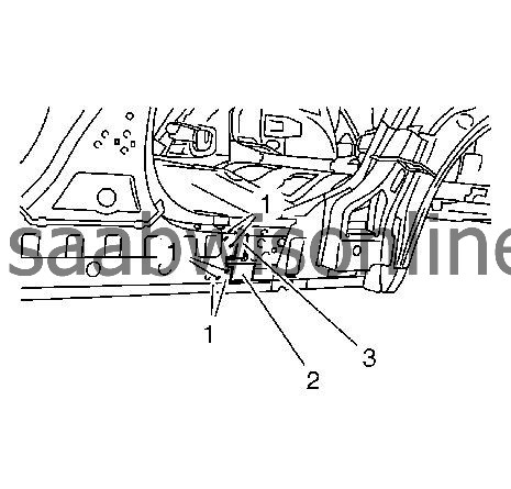
| 7. |
Create a cut line on the rocker outer panel reinforcement (rear) (1). 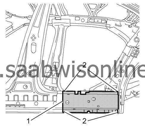
|
|||||||
| 8. |
Locate and drill out all of the necessary factory welds on the rocker outer panel reinforcement (rear) (2).
|
|
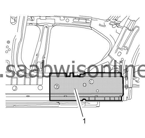
| 9. |
Remove the damaged the rocker outer panel reinforcement (rear) (1).
|
|
| Installation Procedure |
| 1. |
Prepare the new rocker outer panel reinforcement (rear) (1).
|
|
| 2. |
Cut the new rocker outer panel reinforcement (rear) in corresponding to the fit of the original panel. The sectioning joint should be trimmed to allow min. 1 times the metal thickness at the sectioning joint.
|
|
| 3. |
Cut out a 70 mm / 2.8 in in wide backing plates (1) from an unused area of the service part.
|
|
| 4. |
Cut out a 130 mm / 5.1 in in wide backing plates (2) from an unused area of the service part.
|
|
| 5. |
Position the backing plates upper (3) and lower (2) body side.
|
|
| 6. |
Verify the fit of the backing plates upper (3) and lower (2).
|
|
| 7. |
Clamp the backing plates upper (3) and lower (2) into position.
|
|
| 8. |
Drill fastening holes (1) for high strength rivets. 8 holes 6.8 mm / 0.28 in
|
|
| 9. |
Install fasteners in the holes to fix the backing plates.
|
|
| 10. |
Position the new rocker outer panel reinforcement (1) on the vehicle. .
|
|
| 11. |
Verify the fit of the new rocker outer panel reinforcement (1).
|
|
| 12. |
Clamp the new rocker outer panel reinforcement (1) into position
|
|
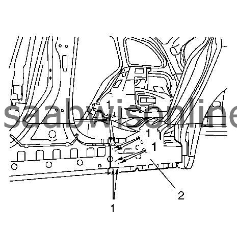
| 13. |
Drill fastening holes (1) for high strength rivets. 8 holes 6.8 mm / 0.28 in
|
|
| 14. |
Remove the new rocker outer panel reinforcement (2) and the backing plates.
|
|||||||
| 15. |
Clean and prepare the attaching surfaces for welding.
|
|
| 16. |
Apply bodywork repair through structural adhesive to body (1). Refer to
Structural Adhesive Body Repairs
.
|
|
| 17. |
Apply bodywork repair through structural adhesive to backing plates (2), (3). Refer to
Structural Adhesive Body Repairs
.
|
|
| 18. |
Position the backing plate upper (3) and lower (2) on the vehicle.
|
|
| 19. |
Verify the fit of the backing plates upper (3) and lower (2).
|
|
| 20. |
Clamp the backing plates upper (3) and lower (2) into position.
|
|
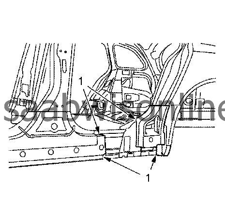
| 21. |
Rivet (1) the backing plates upper (3) and lower (2) on the body
|
|
| 22. |
Position the new rocker outer panel reinforcement (rear) on the vehicle.
|
|||||||
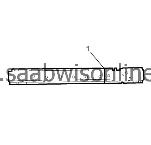
| 23. |
Verify the fit of the new rocker outer panel reinforcement (rear) (1).
|
|
| 24. |
Clamp the new rocker outer panel reinforcement (rear) into position.
|
|
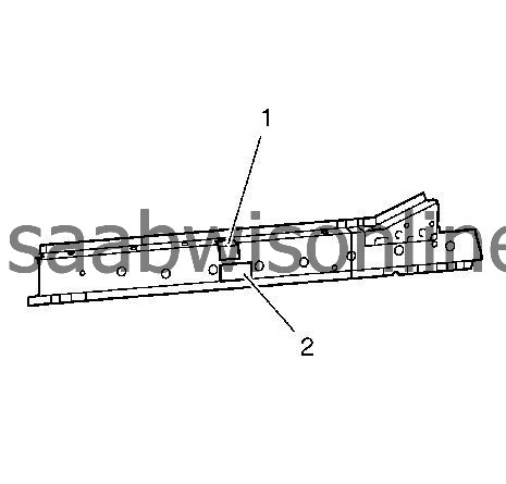
| 25. |
Rivet (1) the rocker outer panel reinforcement (2).
|
|
| 26. |
Spot weld (1) and MIG-braze (2) the rocker outer panel reinforcement (rear) accordingly. Spot weld the area (3). Grind if necessary. 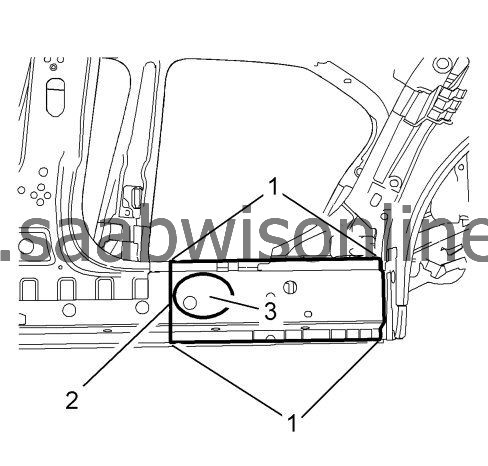
|
|||||||
| 27. |
Install the rocker panel (center). Refer to
Rocker Panel Replacement (Rear)
Rocker Panel Replacement (Front)
Rocker Panel Replacement (Center)
Rocker Panel Replacement (Complete)
|
|
| 28. |
Install the rocker panel (rear). Refer to
Rocker Panel Replacement (Rear)
Rocker Panel Replacement (Front)
Rocker Panel Replacement (Center)
Rocker Panel Replacement (Complete)
.
|
|
| 29. |
Install the rocker outer panel reinforcement (rear, outer). Refer to
Rocker Outer Panel Reinforcement Replacement (Front)
Rocker Outer Panel Reinforcement Replacement (Complete)
Rocker Outer Panel Reinforcement Replacement (Rear)
Rocker Outer Panel Reinforcement Replacement (Rear Outer)
.
|
|
| 30. |
Apply the sealers and anti-corrosion materials to the repair area, as necessary. Refer to
Anti-Corrosion Treatment and Repair (Base)
Anti-Corrosion Treatment and Repair (Corrosion Protection)
.
|
|
| 31. |
Connect the negative battery cable. Refer to
Battery Negative Cable Disconnection and Connection
.
|
|
| 32. |
Enable the SIR system. Refer to
SIR Disabling and Enabling
.
|
|
