Valve Clearance Adjustment (LLU/A16LET)
|
|
Valve Clearance Adjustment (LLU/A16LET)
|
Special Tools
For equivalent regional tools, refer to
Special Tools
.
|
1.
|
|
Note
|
|
Counterhold at hexagon of camshaft.
|
Inspect the 2 valve lash, intake valve cylinder 1.
|
|
|
1.1.
|
Turn the intake camshaft in the direction of engine rotation by the camshaft hexagon until the cams of cylinder 1 are in the test position.
|
|
|
1.2.
|
Insert the
EN-6361
gauge , inspect the valve lash.
|
|
|
1.3.
|
Write down the result.
|
|
2.
|
Inspect the 2 valve lash, intake valve cylinder 3.
|
|
|
2.1.
|
Turn the intake camshaft in the direction of engine rotation by the camshaft hexagon until the cams of cylinder 3 are in the test position.
|
|
|
2.2.
|
Insert the
EN-6361
gauge , inspect the valve lash.
|
|
|
2.3.
|
Write down the result.
|
|
3.
|
Inspect the 2 valve lash, intake valve cylinder 4.
|
|
|
3.1.
|
Turn the intake camshaft in the direction of engine rotation by the camshaft hexagon until the cams of cylinder 4 are in the test position.
|
|
|
3.2.
|
Insert the
EN-6361
gauge , inspect the valve lash.
|
|
|
3.3.
|
Write down the result.
|
|
4.
|
Inspect the 2 valve lash, intake valve cylinder 2.
|
|
|
4.1.
|
Turn the intake camshaft in the direction of engine rotation by the camshaft hexagon until the cams of cylinder 2 are in the test position.
|
|
|
4.2.
|
Insert the
EN-6361
gauge , inspect the valve lash.
|
|
|
4.3.
|
Write down the result.
|
|
5.
|
When replacing the exhaust camshaft, inspect the valve lash of the exhaust valves.
|
|
6.
|
Inspect the 2 valve lash, exhaust valve cylinder 4.
|
|
|
6.1.
|
Turn the exhaust camshaft in the direction of engine rotation by the camshaft hexagon until the cams of cylinder 4 are in the test position.
|
|
|
6.2.
|
Insert the
EN-6361
gauge , inspect the valve lash.
|
|
|
6.3.
|
Write down the result.
|
|
7.
|
Inspect the 2 valve lash, exhaust valve cylinder 2.
|
|
|
7.1.
|
Turn the exhaust camshaft in the direction of engine rotation by the camshaft hexagon until the cams of cylinder 2 are in the test position.
|
|
|
7.2.
|
Insert the
EN-6361
gauge , inspect the valve lash.
|
|
|
7.3.
|
Write down the result.
|
|
8.
|
Inspect the 2 valve lash, exhaust valve cylinder 1.
|
|
|
8.1.
|
Turn the exhaust camshaft in the direction of engine rotation by the camshaft hexagon until the cams of cylinder 1 are in the test position.
|
|
|
8.2.
|
Insert the
EN-6361
gauge , inspect the valve lash.
|
|
|
8.3.
|
Write down the result.
|
|
9.
|
Inspect the 2 valve lash, exhaust valve cylinder 3.
|
|
|
9.1.
|
Turn the exhaust camshaft in the direction of engine rotation by the camshaft hexagon gear until the cams of cylinder 3 are in the test position.
|
|
|
9.2.
|
Insert the
EN-6361
gauge , inspect the valve lash.
|
|
|
9.3.
|
Write down the result.
|
|
10.
|
|
Note
|
|
Note the removal sequence 1-4. Mark the exhaust and intake camshaft bearing caps before removal.
|
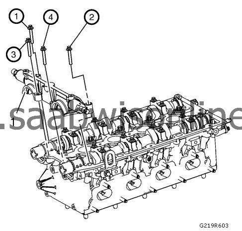
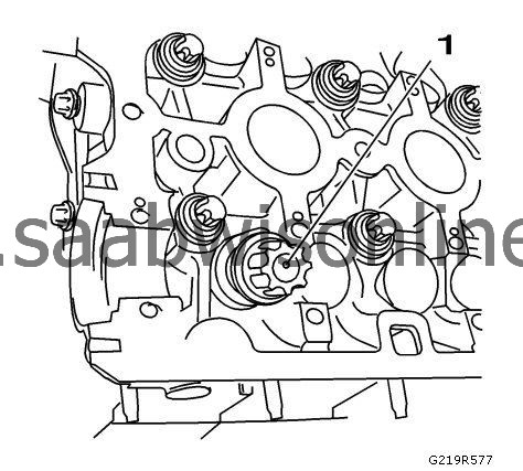
Remove the 4 camshaft bearing front cap fasteners in sequence from the camshaft bearing front cap (1).
|
|
11.
|
Release the intake bearing support by striking it gently with a plastic hammer.
|
|
12.
|
Remove the camshaft bearing front cap.
|
|
13.
|
Detach the intake camshaft bearing caps 1-4 working from outside to inside in a spiral in steps of 1/2 up to 1 turn.
|
|
14.
|
Remove the intake camshaft bearing cover from the cylinder head.
|
|
15.
|
Remove the intake camshaft.
|
|
16.
|
Detach the exhaust camshaft bearing caps 1-4 working from outside to inside in a spiral in steps of 1/2 up to 1 turn.
|
|
17.
|
Remove the exhaust camshaft bearing cover from the cylinder head.
|
|
18.
|
Remove the exhaust camshaft.
|
|
19.
|
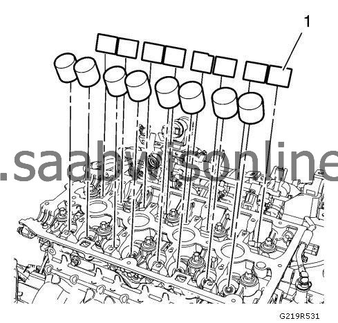
Using the
EN-845
device (1), remove the 16 valve tappets.
|
|
20.
|
Determine valve lifter size.
|
|
|
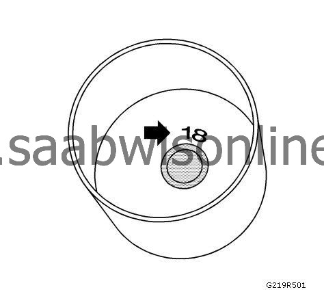
•
|
Measurement of the cup tappet installed
3.12 mm (0.123 in)
, identification number 12. Measured value between cams and cup tappets
+0.31 mm (0.012 in)
=
3.43 mm (0.135 in)
. Required value, valve lash -
0.25 mm (0.010 in)
.
|
|
|
•
|
|
Note
|
|
The identification number, arrow, is on the inside of the valve tappet.
|
Measurement of the new cup tappet =
3.18 mm (0.125 in)
, identification number 18. Use a valve tappet with this dimension or one that is nearest to it.
|
|
1.
|
|
Note
|
|
Observe the correct assignment and coat the sliding surfaces with NEW engine oil.
|
Install the 16 valve lifters (1); use the
EN 845
suction device.
|
