Piston, Connecting Rod, and Bearing Replacement
|
|
Piston, Connecting Rod, and Bearing Replacement
|
Special Tools
|
•
|
EN-43953
Piston Pin Clip Remover/Installer
|
|
•
|
EN-43966-1
Connecting Rod Guides
|
|
•
|
EN-45059
Piston Pin Clip Remover/Installer Adapter
|
|
•
|
EN-46745
Piston Clip Retainer Remover/Installer
|
|
•
|
EN-46745-4
Piston Clip Retainer Remover/Installer Adapter
|
For equivalent regional tools, refer to
Special Tools (LDK, LHU)
.
|
3.
|
Rotate the crankshaft to a position where the connecting rod fasteners are the most accessible.
|
|
4.
|
Mark the connecting rod and cap with the cylinder position. Also mark their orientation. This will ensure the caps and connecting rods are re-assembled properly.
|
|
5.
|
Remove any ridge at the top of the cylinder bore to avoid damage to the piston ring lands.
|
|
6.
|
Remove the connecting rod fasteners.
|
|
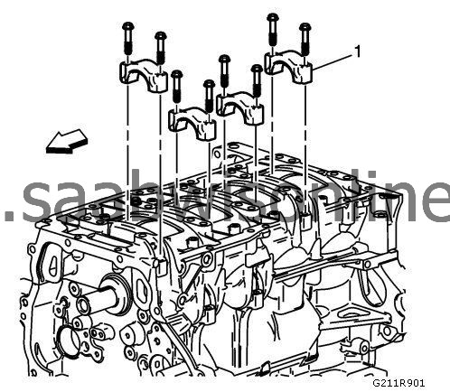
7.
|
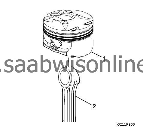
Remove the connecting rod cap (1).
|
|
8.
|
Install
EN-43966-1
guides (1) on the connecting rod fasteners before removing the piston and connecting rod assembly.
|
|
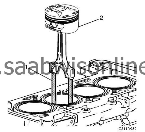
9.
|
Remove the piston and connecting rod assembly (2).
|
|
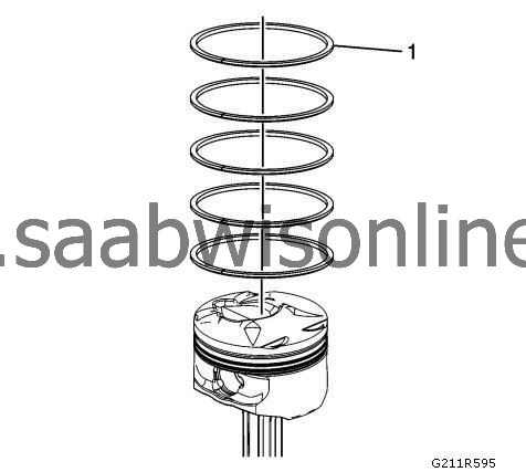
1.
|
 Warning
|
|
Handle the piston carefully. Worn piston rings are sharp and may cause bodily injury.
|
|
|
|
|
|
Disassemble the piston rings (1). Use a suitable tool to expand the rings. The piston rings must not be reused.
|
|
2.
|
|
Note
|
|
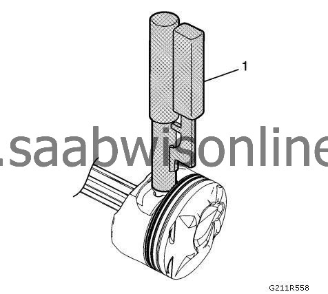
2 piston pin retainers hold the piston pins in place. No special tools are required to remove the piston pins. Ensure that the piston pin is not damaged. Do not reuse the retainers.
|
Remove the piston pin retainers using the
EN-46745
remover (1) and the
EN-46745-4
adapter.
|
|
3.
|
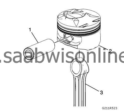
Remove the piston pin (1) and connecting rod (3) from the piston (2).
|
|
Connecting Rod Measurement
|
|
1.
|
|
Warning
|
|
Wear safety glasses when using compressed air, as flying dirt particles may cause eye injury.
|
|
|
|
|
|
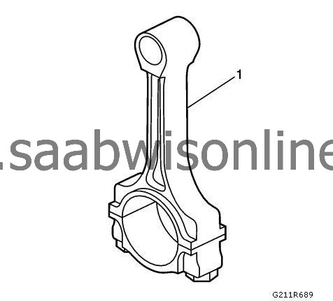
Clean the connecting rods (1) in solvent and dry with compressed air.
|
|
2.
|
Inspect the connecting rods for the following conditions:
|
|
|
•
|
Signs of being twisted, bent, nicked, or cracked
|
|
|
•
|
Scratches or abrasion on the rod bearing seating surface
|
|
3.
|
If the connecting rod bores contain minor scratches or abrasions, clean the bores in a circular direction with fine emery cloth. DO NOT scrape the rod or rod cap.
|
|
4.
|
If the beam of the rod is scratched or has other damage replace the connecting rod.
|
|
5.
|
Measure the piston pin to connecting rod bore using the following procedure:
|
|
|
•
|
Using an outside micrometer, take two measurements of the piston pin in the area of the connecting rod contact.
|
|
|
•
|
Using an inside micrometer, measure the connecting rod piston pin bore.
|
|
|
•
|
Subtract the piston pin diameter from the piston pin bore diameter.
|
|
|
•
|
The clearance should not be more than
0.021 mm (0.0008 in)
.
|
|
6.
|
If there is excessive clearance, replace the piston pin.
|
|
7.
|
If there is still excessive clearance, replace the connecting rod.
|
|
1.
|
Clean the piston skirts and the pins with a cleaning solvent. DO NOT wire brush any part of the piston.
|
|
2.
|
Clean the piston ring grooves with a groove cleaner. Ensure the oil ring holes and slots are clean.
|
|
3.
|
Inspect the pistons for the following conditions:
|
|
|
•
|
Cracked ring lands, skirts, or pin bosses
|
|
|
•
|
Ring grooves for nicks, burrs that may cause binding
|
|
|
•
|
Warped or worn ring lands
|
|
|
•
|
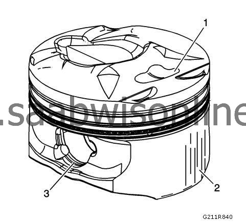
Eroded areas at the top of the piston (1)
|
|
|
•
|
Scuffed or damaged skirts (2)
|
|
|
•
|
Worn piston pin bores (3)
|
|
4.
|
Replace pistons that show any signs or damage or excessive wear.
|
|
5.
|
Measure the piston pin bore to piston pin clearances using the following procedure:
|
|
|
•
|
Piston pin bores and pins must be free of varnish or scuffing.
|
|
|
•
|
Use an outside micrometer to measure the piston pin in the piston contact areas.
|
|
|
•
|
Using an inside micrometer, measure the piston pin bore.
|
|
|
•
|
Subtract the measurement of the piston pin bore from the piston pin. The clearance should be within
0.002 mm - 0.012 mm (0.00007 in - 0.00047 in)
.
|
|
|
•
|
If the clearance is excessive, determine which component is out of specification.
|
|
6.
|
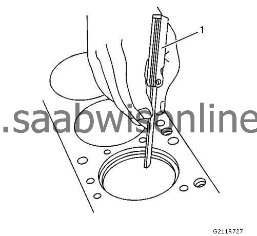
Measure the piston ring end gap using the following procedure:
|
|
|
•
|
Place the piston ring in the area of the bore where the piston ring will travel, approximately 25 mm or 1 inch down from the deck surface. Ensure the ring is square with the cylinder bore by positioning the ring with the piston head
|
|
|
•
|
Measure the end gap of the piston ring with feeler gauges (1). Compare the measurements with those provided below.
|
|
|
•
|
The top compression ring end gap should be
0.20 mm - 0.35 mm (0.0078 in - 0.0138 in)
.
|
|
|
•
|
The second compression ring end gap should be
0.35 mm - 0.55 mm (0.0137 in - 0.0216 in)
.
|
|
|
•
|
The oil ring end gap should be
0.25 mm - 0.76 mm (0.0098 in - 0.029 in)
.
|
|
|
•
|
If the clearance exceeds the provided specifications, the piston rings must be replaced.
|
|
|
•
|
Repeat the procedure for all the piston rings.
|
|
7.
|
Measure the piston ring side clearance using the following procedure:
|
|
|
•
|
Roll the piston ring (2) entirely around the piston ring groove. If any binding is caused by a distorted piston ring, replace the ring.
|
|
|
•
|
With the piston ring on the piston, use feeler gauges (1) to measure clearance at multiple locations.
|
|
|
•
|
The clearance between the surface of the top piston ring and the ring land should be no greater than
0.055 mm (0.0022 in)
.
|
|
|
•
|
If the clearance is greater than specifications, replace the piston ring.
|
|
|
•
|
If the new ring does not reduce the top ring side clearance to
0.055 mm (0.0022 in)
or less, install a new piston.
|
|
8.
|
The top compression ring may be installed with either side up. There is a locating dimple on the second compression ring near the end for identification of the top side. Install the second compression ring with the dimple facing up.
|
|
9.
|
The clearance between the surface of the second piston ring and the ring land should be no greater than
0.032 mm (0.0012 in)
.
|
|
10.
|
If the new ring does not reduce the clearance to
0.032 mm (0.0012 in)
0.032 mm (0.0012 in) or less, install a new piston.
|
|
11.
|
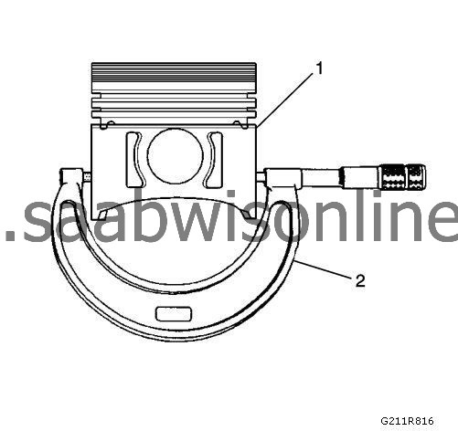
Measure piston width using the following procedure:
|
|
|
•
|
Using an outside micrometer (2), measure the width of the piston (1)
12.5 mm (0.4925 in)
above the bottom of the piston skirt at the thrust surface perpendicular to the centerline of the piston pin.
|
|
|
•
|
Compare the measurement of the piston to its original cylinder by subtracting the piston width from the cylinder diameter.
|
|
|
•
|
The proper clearance specification for the piston is
0.010 mm - 0.041 mm (0.0006 in - 0.0016 in)
.
|
|
12.
|
If the clearance obtained through measurement is greater than these specifications and the cylinder bores are within specification, replace the piston.
|
|
2.
|
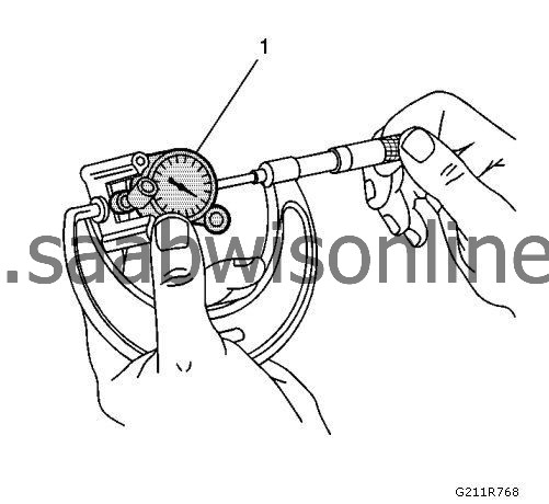
Using a bore gauge (1), measure the cylinder bore diameter. Measure at a point
64 mm (2.5 in)
from the top of the cylinder bore.
|
|
3.
|
Measure the bore gauge (1) with a micrometer and record the reading.
|
|
4.
|
With a micrometer (2) or caliper at a right angle to the piston, measure the piston (1)
14 mm (0.570 in)
from the bottom of the skirt.
|
|
5.
|
Subtract the piston diameter from the cylinder bore diameter in order to determine piston-to-bore clearance.
|
|
7.
|
If the proper clearance cannot be obtained, select another piston and measure for the clearances.
|
|
8.
|
If the proper fit cannot be obtained, hone the cylinder bore or replace the cylinder block.
|
|
9.
|
When the piston-to-cylinder bore clearance is within specifications, mark the top of the piston using a permanent marker for installation to the proper cylinder. Refer to
Separating Parts
.
|
|
Piston and Connecting Rod Assemble
|
|
1.
|
|
Note
|
|
Install the piston onto the connecting rod with the arrow oriented toward the front of the engine.
|
Assemble the connecting rod (2) and the piston (1).
|
|
2.
|
|
Warning
|
|
Install the piston pin retainers correctly in the retaining groove during assembly in order to avoid engine damage.
|
|
|
|
|
|
Use the following procedure to assemble the piston pin and the retainer:
|
|
|
•
|
Coat the piston pin with oil.
|
|
|
•
|
Using the
EN-46745
installer (1) and the
EN-46745-4
adapter , install one side of one piston pin retainer into the retaining groove. Rotate the retainer until it is fully seated in the groove.
|
|
|
•
|
Install the connecting rod and the piston pin. Push the piston pin until it bottoms in the previously installed retainer.
|
|
|
•
|
Using the
EN-46745
installer and the
EN-46745-4
adapter , install the second piston pin retainer.
|
|
|
•
|
Ensure that the piston moves freely.
|
|
3.
|
|
Warning
|
|
Use a piston ring expander to install the piston rings. The rings may be damaged if expanded more than necessary.
|
|
|
|
|
|
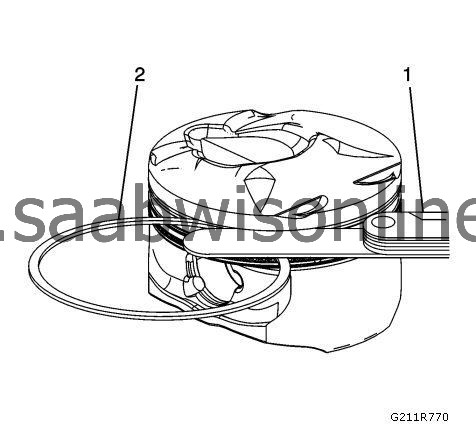
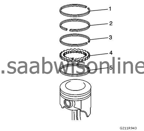
Install the following components of the oil control ring assembly - bottom ring:
|
|
|
•
|
The lower oil control ring (4).
|
|
|
•
|
The upper control ring (3).
|
|
4.
|
Install the lower compression ring - second ring (2). Place the manufacturer's mark facing up.
|
|
5.
|
Install the upper compression ring - top ring (1).
|
|
1.
|
Install the NEW connecting rod bearings.
|
|
|
•
|
Install the bearing inserts into the connecting rod and the connecting rod cap.
|
|
|
•
|
Lubricate the connecting rod bearings with engine oil.
|
|
2.
|
Install the
EN-43966-1
guides (1) into the connecting rod fastener holes. This protects the crankshaft journal during piston and connecting rod installation.
|
|
3.
|
Install the
EN-43953
compressor , the piston (2), and the connecting rod to the correct bore.
|
|
|
•
|
Stagger each piston ring end gap equally around the piston.
|
|
|
•
|
Lubricate the piston and the piston rings with engine oil.
|
|
|
•
|
Do not disturb the piston ring end gap location.
|
|
|
•
|
The piston must be installed so that the mark on the top of the piston faces the front of the engine.
|
|
|
•
|
Place the piston in its matching bore.
|
|
|
•
|
Tap the piston into its bore with a hammer handle. Guide the connecting rod to the connecting rod journal while tapping the piston into place.
|
|
|
•
|
Hold the
EN-43953
compressor against the engine block until all the rings have entered the cylinder bore.
|
|
|
•
|
Remove the connecting rod guides from the connecting rod fastener holes.
|
|
4.
|
Install the connecting rod cap (1).
|
|
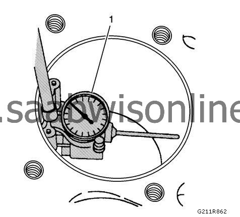
5.
|
Refer to
Fastener Caution
.
|
Note
|
|
Always use NEW fasteners.
|
Install NEW connecting rod fasteners with
EN-45059
angle meter and tighten the fasteners to
25 Nm (18 lb ft) plus 100 degrees
.
|
|
6.
|
Install the remaining connecting rods and piston assemblies. The correct clearance is
0.07 mm - 0.37 mm (0.0027 in - 0.0145 in)
.
|