Valve Stem Oil Seal and Valve Spring Replacement
|
|
Valve Stem Oil Seal and Valve Spring Replacement
|
Special Tools
|
•
|
EN-840
Valve Stem Oil Seal Remover
|
|
•
|
EN-6086
Spring and Wedge Replacer
|
|
•
|
EN-6152
Valve Stem Oil Seal Installer
|
|
•
|
EN-6171
Valve Spring Key Solvent
|
For equivalent regional tools, refer to
Special Tools (LDK, LHU)
.
|
Note
|
|
Clean working is condition.
|
|
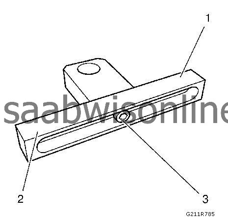
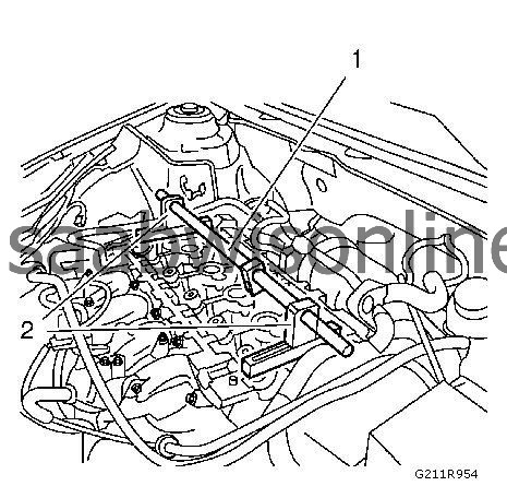
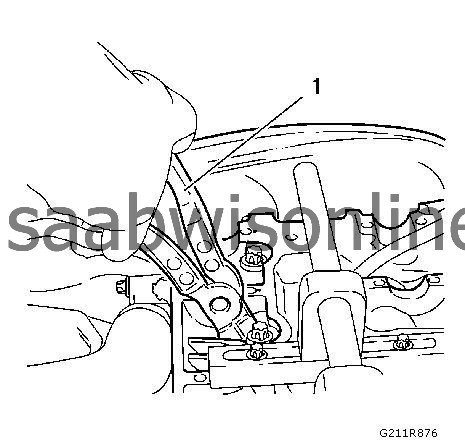
5.
|
Tighten one of the support head (1) in the center of the rail (2) with the fastener (3).
|
|
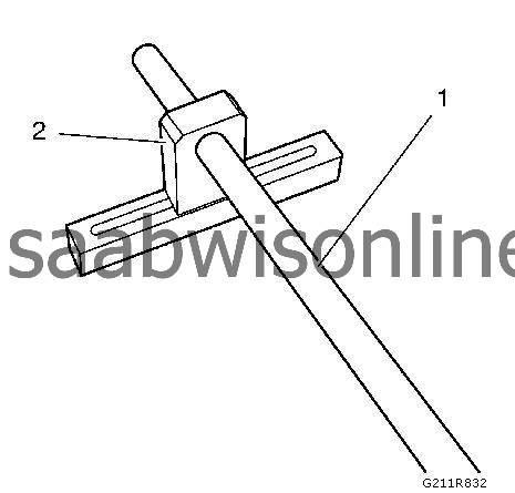
6.
|
Install the
EN-6086-5
mounting shaft (1) to one of the
EN-6086-6
supports (2).
|
|
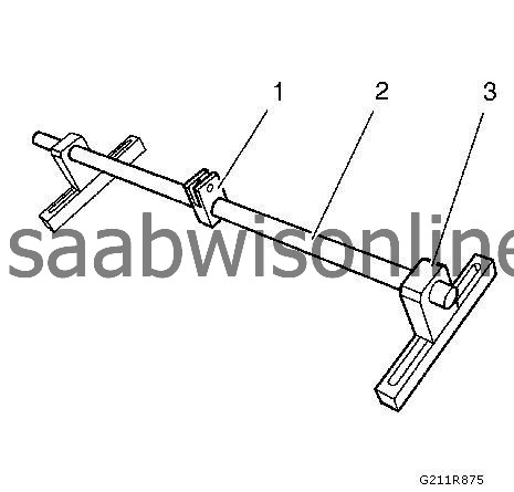
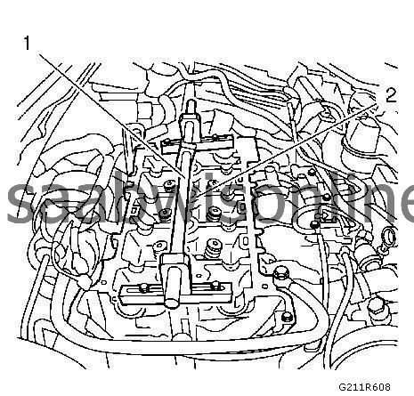
7.
|
Install the
EN-6086-8
knuckle (1) to the
EN-6086-5
mounting shaft (2) and install the second support (3) to the mounting shaft (2).
|
|
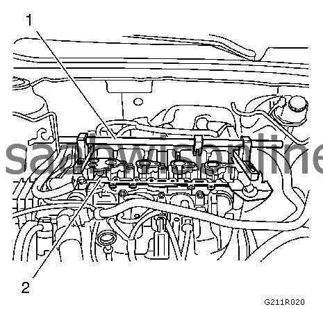
8.
|
Install the lever arm bracket (1) to the cylinder head (2).
|
|
|
•
|
The fixed side of the lever arm bracket install on the left side of the cylinder head but do not tighten yet.
|
|
|
•
|
The not fixed side of the lever arm bracket install on the right side of the cylinder head but do not tighten yet.
|
|
9.
|
Fix the
EN-6086-5
mounting shaft (1) with both support head fasteners (2).
|
|
10.
|
Align the lever arm bracket (1) in the center of the cylinder head on the basis of the spark plug drillings (2).
|
|
11.
|
Tighten both
EN-6086-6
supports to the cylinder head.
|
|
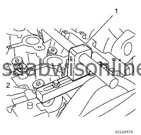
12.
|
Fix the second support head (1) to the rail (2).
Release the heated oxygen sensor 1 electrical connector from the cylinder head.
|
|
13.
|
|
Note
|
|
All wheels must be in contact with the ground.
|
Fix the crankshaft.
Use a suitable tool.
|
|
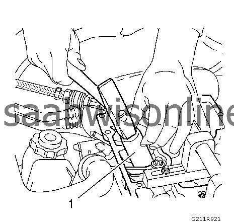
14.
|
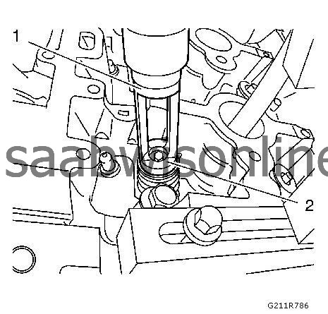
Install the
EN-6086-15
compressed air adapter (1) to the spark plug drill (2) of the first cylinder.
|
|
15.
|
Subject the first cylinder with compression air.
|
|
16.
|
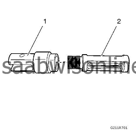
Install the
EN-6086-12
adapter part small (1) to the
EN-6086-11
removal part small (2).
|
|
17.
|
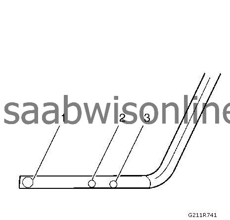
Install the
EN-6086-12
adapter part small and the
EN-6086-11
removal part small to position 3 to the
EN-6086-7
lever arm. Fasten the tools with
EN-6086-2
pin.
|
|
18.
|
lnstall the
EN-6086-7
lever arm to the
EN-6086-8
knuckle.
|
|
|
•
|
Use the position 1 of the lever arm.
|
|
|
•
|
Fasten the tools with
EN-6086-2
pin.
|
|
19.
|
|
Note
|
|
Note the installation construction units position of the valve stem keys, valve spring retainer and valve spring.
|
Set the
EN-6086-11
removal part small (1) on the intake valve spring retainer (2) on the left side of the first cylinder.
|
|
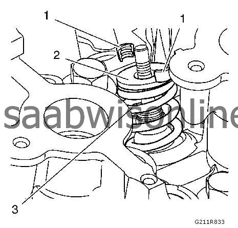
20.
|
To remove the valve stem key (1), valve spring retainer (2) and valve spring (3) press the lever arm downward.
|
|
21.
|
|
Note
|
|
Do not use magnetic tools.
|
If the valve stem key are out fallen, remove the valve stem keys with
EN-6086-13
round awl and
EN-6086-14
special calliper.
|
|
22.
|
Set the
EN-6086-11
removal part small on that intake valve spring retainer on the right side to the first cylinder.
|
|
23.
|
To remove from the valve stem keys, valve spring retainer and valve spring press the lever arm downward.
|
|
24.
|
|
Note
|
|
Do not use magnetic tools.
|
If the valve stem key has become loose, remove the valve stem keys with
EN-6086-13
round awl and
EN-6086-14
special calliper.
|
|
25.
|
Remove both valve stem oil seal rings with
EN-840
valve stem oil seal remover (1) from the cylinder head.
|
|
26.
|
Install the small part of the
EN-6086-12
adapter and
EN-6086-11
, the small part to be removed in position 1 on the
EN-6086-7
lever. Fasten the tools using the
EN-6086-2
pin.
|
|
27.
|
lnstall the
EN-6086-7
lever arm to the
EN-6086-8
knuckle.
|
|
|
•
|
Use the position 3 to the lever arm.
|
|
|
•
|
Fasten the tools with
EN-6086-2
pin.
|
|
28.
|
|
Note
|
|
Note the position of the valve stem keys, valve spring retainer and valve spring.
|
Set the
EN-6086-11
removal part small on that exhaust valve spring retainer on the left side at the first cylinder.
|
|
29.
|
To remove the valve stem key, valve spring retainer and valve spring press the lever arm upward.
|
|
30.
|
|
Note
|
|
Do not use magnetic tools.
|
If the valve stem key are loosen, remove the valve stem keys with
EN-6086-13
round awl and
EN-6086-14
special calliper.
|
|
31.
|
Set the
EN-6086-11
removal part small on that exhaust valve spring retainer on the right side to the first cylinder.
|
|
32.
|
To remove the valve stem keys, valve spring retainer and valve spring press the lever arm upward.
|
|
33.
|
|
Note
|
|
Do not use magnetic tools.
|
If the valve stem key are loosen, remove the valve stem keys with
EN-6086-13
round awl and
EN-6086-14
special calliper.
|
|
34.
|
Remove the both valve stem oil seal rings with
EN-840
valve stem oil seal remover from the cylinder head.
|
|
1.
|
|
Note
|
|
Do not press the valve downward.
|
Install with
EN-6152
valve stem oil seal installer (1) the new valve stem oil seal rings to the cylinder head.
|
|
|
•
|
Press the valve stem oil seal ring with the finger downward.
|
|
|
•
|
The
EN-6152
valve stem oil seal installer must rest upon at the lower edge of the valve stem oil seal ring.
|
|
|
•
|
Knock with a rubber hammer on the
EN-6152
valve stem oil seal installer to sit the valve stem oil seal ring to the cylinder head.
|
|
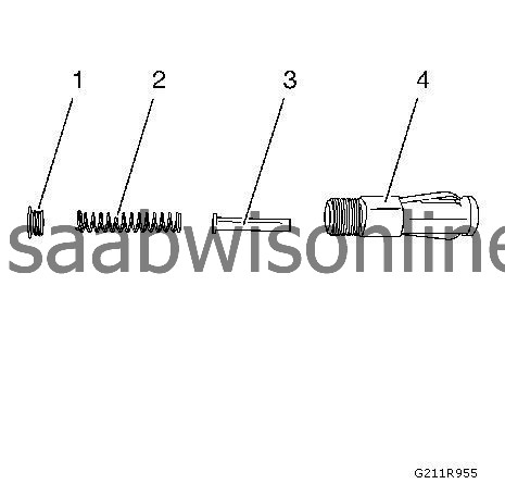
2.
|
Install
EN-6086-100-15
pressure adapter 6 (3) to the
EN-6086-100-10
mounting part (4).
|
|
|
•
|
Remove the fastener (1) from the mounting part (4).
|
|
|
•
|
Remove the spring (2) from the mounting part (4).
|
|
|
•
|
Install the pressure adapter 6 (3) into the mounting part (4).
|
|
|
•
|
Install the spring (2) into the mounting part (4).
|
|
|
•
|
Install the fastener (1) to the mounting part (4).
|
|
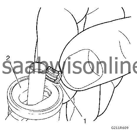
3.
|
|
Note
|
|
Only one attempt. If the attempt failed, repeat step 3 to 8 for the exhaust left side and step 9 to 13 for the exhaust right side.
|
Install the valve stem keys (1) to the
EN-6086-100-10
mounting part (2).
|
|
|
•
|
Pull the ring back that the the springs are loosen.
|
|
|
•
|
Install the valve stem keys with the narrow side upward.
|
|
|
•
|
Pull the ring forward till the springs are the valve stem keys locking.
|
|
4.
|
Install the
EN-6086-100-10
mounting part to the
EN-6086-12
adapter part.
|
|
5.
|
Install both parts to the
EN-6086-7
lever arm.
|
|
6.
|
Install the left exhaust valve spring and the left exhaust valve retainer to the cylinder head.
|
|
7.
|
Set the
EN-6086-100-15
pressure adapter to the left exhaust valve.
|
|
8.
|
Press the lever arm up to audibly engage the left valve stem keys.
|
|
9.
|
Install the valve stem keys to the
EN-6086-100-10
mounting part.
|
|
|
•
|
Pull the ring back that the the springs are loosen.
|
|
|
•
|
Install the valve stem keys with the narrow side upward.
|
|
|
•
|
Pull the ring forward till the springs are the valve stem keys locking.
|
|
10.
|
Install the
EN-6086-100-10
mounting part to the
EN-6086-12
adapter part.
|
|
11.
|
Install both parts to the
EN-6086-7
lever arm.
|
|
12.
|
Install the right exhaust valve spring and the right exhaust valve retainer to the cylinder head.
|
|
13.
|
Set the
EN-6086-100-15
pressure adapter to the right exhaust valve.
|
|
14.
|
Press the lever arm up to audibly engage the right valve stem keys.
|
|
15.
|
Remove the
EN-6086-7
lever arm from the
EN-6086-8
knuckle.
|
|
16.
|
lnstall the
EN-6086-7
lever arm (1) to the
EN-6086-8
knuckle (2).
|
|
|
•
|
Use the position 1 from the lever arm.
|
|
|
•
|
Fasten the tools with
EN-6086-2
pin.
|
|
17.
|
|
Note
|
|
Do not press the valve downward.
|
Install with
EN-6152
valve stem oil seal installer (1) the new valve stem oil seal rings to the cylinder head.
|
|
|
•
|
Press the valve stem oil seal ring with the finger downward.
|
|
|
•
|
The
EN-6152
valve stem oil seal installer must rest upon at the lower edge of the valve stem oil seal ring.
|
|
|
•
|
Knock with a rubber hammer on the
EN-6152
valve stem oil seal installer to sit the valve stem oil seal ring to the cylinder head.
|
|
18.
|
|
Note
|
|
Only one attempt. If the attempt failed, repeat step 18 to 23 for the intake left side and step 24 to 29 for the intake right side.
|
Install the valve stem keys to the
EN-6086-100-10
mounting part.
|
|
|
•
|
Pull the ring back that the the springs are loosen.
|
|
|
•
|
Install the valve stem keys with the narrow side upward.
|
|
|
•
|
Pull the ring forward till the springs are the valve stem keys locking.
|
|
19.
|
Install the
EN-6086-100-10
mounting part to the
EN-6086-12
adapter part.
|
|
20.
|
Install both parts to the
EN-6086-7
lever arm.
|
|
21.
|
Install the left intake valve spring and the left intake valve retainer to the cylinder head.
|
|
22.
|
Set the
EN-6086-100-15
pressure adapter to the left intake valve.
|
|
23.
|
Press the lever arm down to audibly engage the left valve stem keys.
|
|
24.
|
Install the valve stem keys (1) to the
EN-6086-100-10
mounting part (2).
|
|
|
•
|
Pull the ring back that the the springs are loosen.
|
|
|
•
|
Install the valve stem keys with the narrow side upward.
|
|
|
•
|
Pull the ring forward till the springs are the valve stem keys locking.
|
|
25.
|
Install the
EN-6086-100-10
mounting part to the
EN-6086-12
adapter part.
|
|
26.
|
Install both parts to the
EN-6086-7
lever arm.
|
|
27.
|
Install the right intake valve spring and the right intake valve retainer to the cylinder head.
|
|
28.
|
Set the
EN-6086-100-15
pressure adapter to the right intake valve.
|
|
29.
|
Press the lever arm down to audibly engage the right valve stem keys.
|
|
30.
|
Remove the
EN-6086-7
lever arm from the
EN-6086-8
knuckle.
|
|
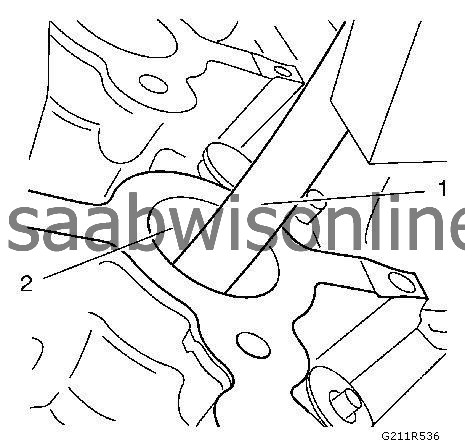
31.
|
To replace the valve stem oil seals of the cylinders 2 and 3 turn the crankshaft by
180 degrees
.
|
|
|
•
|
Set 2 marks (1), by
180 degrees
transferred, at the oil pump housing.
|
|
|
•
|
Set 1 mark (2) at the crankshaft balancer.
|
|
|
•
|
A second mechanic must hold the primary timing chain upward.
|
|
|
•
|
Turn clock wise the timing chain
180 degrees
.
|
|
32.
|
To remove the valve stem oil seals repeat the steps from removal 15 to 35.
|
|
33.
|
To install the valve stem oil seals repeat the steps from installation 1 to 31.
|
|
34.
|
Turn back the crankshaft
180 degrees
against clockwise direction after the exchange of the valve stem sealings of the cylinder 2 and 3.
A second mechanic must hold the primary timing chain upward.
|
|
35.
|
Remove the lever arm bracket.
|
