Cylinder Head Replacement (LBY/A20DTR)
|
|
Cylinder Head Replacement (LBY/A20DTR)
|
 Warning
|
|
Always wear safety goggles when working with fuel in order to protect the eyes from fuel splash.
|
|
|
|
|
|
|
Warning
|
|
Fuel Vapors can collect while servicing fuel system parts in enclosed areas such as a trunk. To reduce the risk of fire and increased exposure to vapors:
|
|
•
|
Use forced air ventilation such as a fan set outside of the trunk.
|
|
•
|
Plug or cap any fuel system openings in order to reduce fuel vapor formation.
|
|
•
|
Clean up any spilled fuel immediately.
|
|
•
|
Avoid sparks and any source of ignition.
|
|
•
|
Use signs to alert others in the work area that fuel system work is in process.
|
|
|
|
|
|
|
Warning
|
|
Place a dry chemical (Class B) fire extinguisher nearby before performing any on-vehicle service procedures. Failure to follow these precautions may result in personal injury.
|
|
|
|
|
|
|
Warning
|
|
Do not allow smoking or the use of open flames in the area where work on the fuel or EVAP system is taking place. Anytime work is being done on the fuel system, disconnect the negative battery cable, except for those tests where battery voltage is required.
|
|
|
|
|
|
|
Warning
|
|
Fuel coming from the tank under high pressure can cause serious injuries to the skin and eyes. ALWAYS relieve the pressure in the fuel system before removing components under high fuel pressure.
|
|
|
|
|
|
|
2.
|
Disconnect the negative battery cable. Refer to
Battery Negative Cable Disconnection and Connection
.
|
Warning
|
|
With a pressurized cooling system, the coolant temperature in the radiator can be considerably higher than the boiling point of the solution at atmospheric pressure. Removal of the surge tank cap, while the cooling system is hot and under high pressure, causes the solution to boil instantaneously with explosive force. This will cause the solution to spew out over the engine, the fenders, and the person removing the cap. Serious bodily injury may result.
|
|
|
|
|
|
|
|
3.
|
Take the cap off the expansion tank to release any pressure.
|
|
8.
|
Remove the lower coolant hose between the radiator and the cylinder head from the cylinder head side.
|
|
9.
|
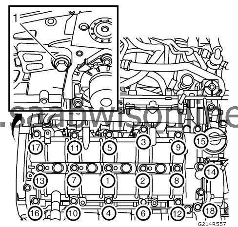
Remove the bolts (1) holding the crankcase ventilation pipe and bend it aside.
|
|
10.
|
Remove the brake servo hose from the vacuum pump and bend it aside.
|
|
11.
|
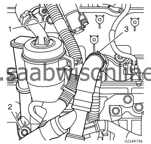
Undo and remove the crankcase ventilation hose (1) from the oil trap and the bolts (2) holding the oil trap bracket and remove the cooling hose (3).
|
|
12.
|
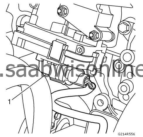
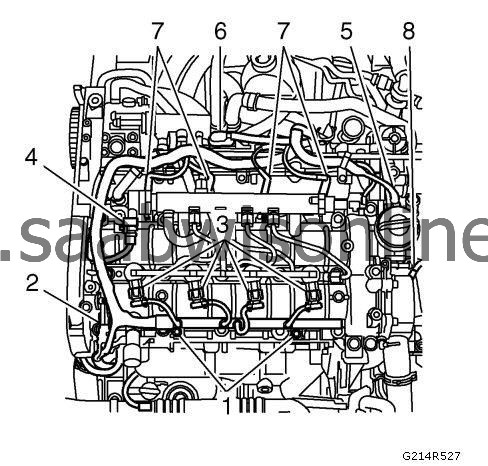
Remove the connector (1) to the combustion circulation actuator.
|
|
13.
|
Remove the cable duct retaining screws (1).
|
|
14.
|
Remove the following connectors:
|
|
|
•
|
Camshaft position sensor (2)
|
|
|
•
|
Fuel pressure control valve (4)
|
|
|
•
|
Throttle body actuator unit (5)
|
|
|
•
|
Glow plug connector (7)
|
|
|
•
|
Coolant temperature sensor (8)
|
|
15.
|
Fold away the engine wiring harness.
|
|
16.
|
|
Note
|
|
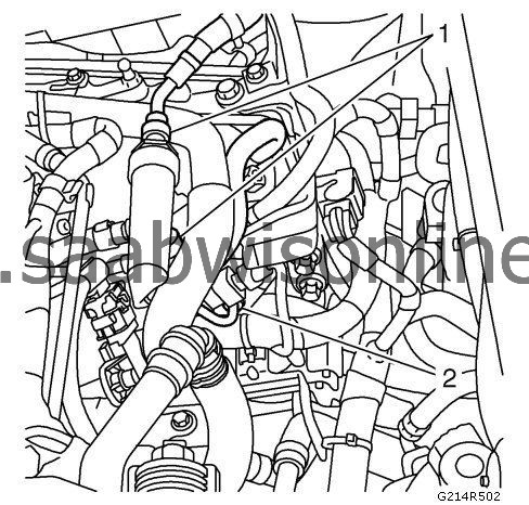
If the injectors are to be refitted, mark the injectors so that they can be refitted to the same cylinder.
|
Remove the fuel return hoses (1) from the return fuel collector and the fuel delivery pipe (2) between the pump and the fuel rail.
|
|
19.
|
Remove the bolt (1) between the fuel pump bracket and cylinder head, screw out the spacer bolt a few turns.
|
|
20.
|
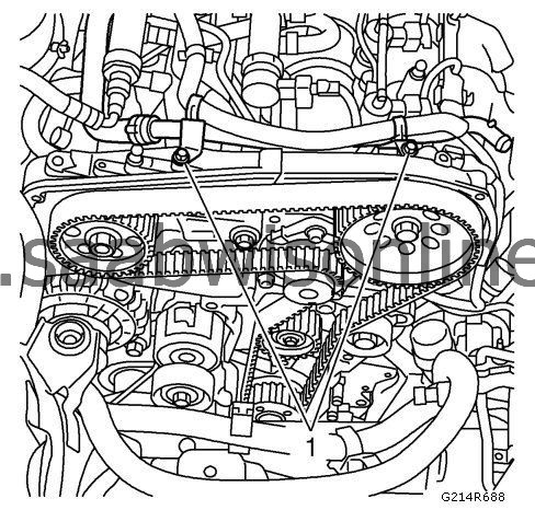
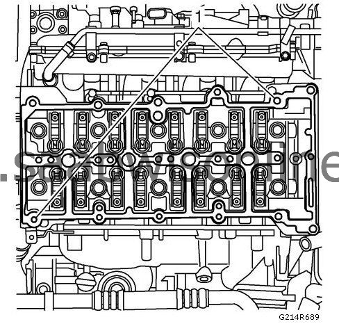
Undo and remove the camshaft housing and guide sleeves. Loosen bolts alternately in order as illustrated.
|
|
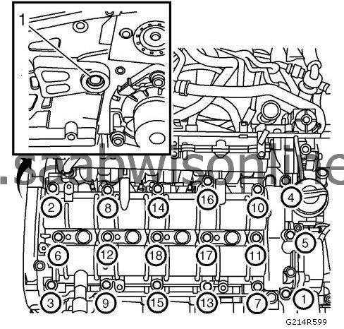
21.
|
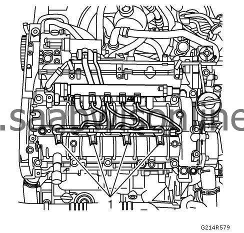
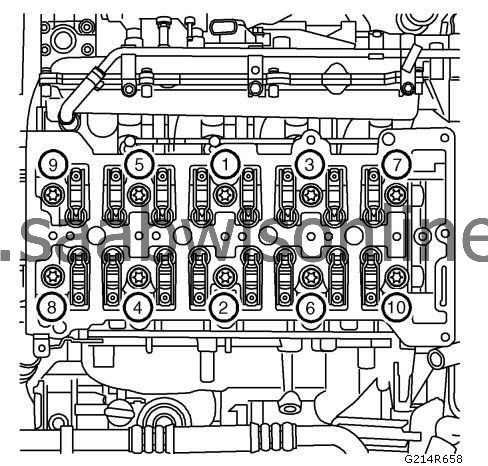
Remove the cylinder head by undoing the bolts in the illustrated order.
|
|
22.
|
|
Note
|
|
Do not confuse the engine block guide sleeves with the camshaft guide sleeves.
|
Carefully lift off the cylinder head.
|
|
23.
|
Remove the engine block guide sleeves.
|
|
1.
|
Clean the bolt holes in the cylinder block.
|
|
2.
|
Clean away any gasket remains from the cylinder head and cylinder block sealing surfaces.
|
|
3.
|
|
Note
|
|
Do not confuse the engine block guide sleeves with the camshaft guide sleeves.
|
Check the flatness of the cylinder head and cylinder block with a steel rule and inspect for damage to the sealing surfaces.
|
|
4.
|
Place the guide sleeves (1) on the engine block.
|
|
5.
|
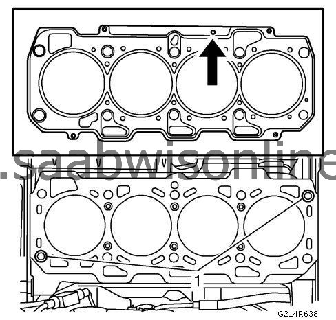
Fit a new gasket with the same thickness as the old one.
|
|
6.
|
Position the cylinder head on the cylinder block.
|
|
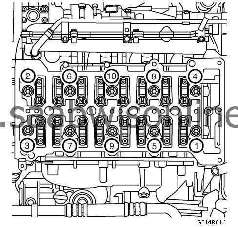
7.
|
Tighten the cylinder head bolts in sequence 1-10.
Tighten
|
|
4.
|
Clean the cylinder head and camshaft housing sealing surfaces from any gasket residue.
|
|
5.
|
Fit the guide sleeves (1) and fit a new gasket onto the cylinder head.
|
|
6.
|
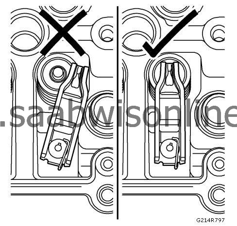
Check that all the rocker arms are positioned correctly on the valve stems.
|
|
7.
|
Fit the camshaft housing, tighten the bolts alternately. Make sure the guide sleeves are positioned correctly in the camshaft housing.
Tighten
25 Nm (18 lb ft)
|
|
8.
|
Screw in the spacer sleeve against the cylinder head and fit the bolt (1).
|
|
12.
|
Fit the fuel delivery pipe (2) between the pump and the fuel rail.
Tighten
25 Nm (18 lb ft)
|
|
13.
|
Fit the fuel return hoses (1) to the return fuel collector.
|
|
14.
|
Fold the engine wiring harness back in place and fit the following connectors:
|
|
|
•
|
Camshaft position sensor (2)
|
|
|
•
|
Fuel pressure control valve (4)
|
|
|
•
|
Throttle body actuator unit (5)
|
|
|
•
|
Glow plug connector (7)
|
|
|
•
|
Coolant temperature sensor (8)
|
|
15.
|
Fit the cable duct retaining screws (1) and fix the wiring harness.
|
|
16.
|
Fit the connector (1) to the combustion circulation actuator.
|
|
17.
|
Bend the oil trap bracket back in place and fit the crankcase ventilation hose (1) from the oil trap and the bolts (2) holding the oil trap bracket and remove the cooling hose (3).
|
|
19.
|
Fit the crankcase ventilation hoses onto the cylinder head.
|
|
20.
|
Fit the brake servo hose to the vacuum pump. Secure the hose.
|
|
21.
|
Fit the bolts (1) holding the crankcase ventilation pipe and crankcase ventilation pipe and secure the wiring harness.
|
|
23.
|
Fit the lower coolant hose between the radiator and the cylinder head to the cylinder head side.
|
|
26.
|
Check that there are no leaks from engine oil or coolant fluid.
|
|
28.
|
Connect the computer and erase any trouble codes.
|