Piston, Connecting Rod, and Bearing Removal
|
|
Piston, Connecting Rod, and Bearing Removal
|
Special Tools
EN 46121
Connecting Rod Guide Pin Set
For equivalent regional tools, refer to
Special Tools
.
|
1.
|
|
Note
|
|
•
|
An arrow/dot showing proper piston orientation is located on the top of the piston.
|
|
•
|
If the connecting rod bearings have been used in a running engine, you must replace them with NEW connecting rod bearings for reassembly.
|
Before removing the connecting rods, check the connecting rod side clearance using the following procedure:
|
|
|
1.1.
|
Tap the connecting rod to one end of the crankshaft journal with a dead-blow or wooden hammer.
|
|
|
1.2.
|
Using feeler gauges, measure the clearance between the crankshaft counterweight and the connecting rod.
|
|
|
1.5.
|
If the connecting rod width is significantly smaller than specified and severe wear is present on the side of the connecting rod, replace the connecting rod.
|
|
|
1.6.
|
If the connecting rod width is within specification and excessive scoring is present on the crankshaft journals, replace the crankshaft.
|
|
2.
|
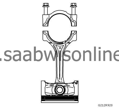
Using a marker, number each piston face. Draw an arrow along the centerline of the piston pointing toward the front of the engine.
|
|
3.
|
 Warning
|
|
Do not use a stamp, punch or any other method that may distort or stress the connecting rod or connecting rod cap. Extensive engine damage may result from a connecting rod that is distorted or stressed.
|
|
|
|
|
|
Mark the cylinder number on the connecting rod and the connecting rod cap with a scribe, paint stick or permanent marker.
|
|
4.
|
|
Warning
|
|
Powdered metal connecting rods have rod bolts which yield when torqued. If the rod bolts are loosened or removed the rod bolts must be replaced. Rod bolts that are not replaced will not torque to the correct clamp load and can lead to serious engine damage.
|
|
|
|
|
|
Remove the connecting rod bolts.
|
|
5.
|
|
Note
|
|
The connecting rod caps must remain with the original connecting rod.
|
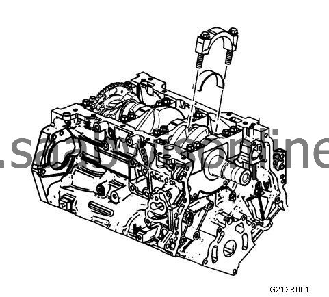
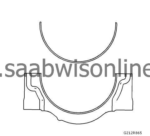
Remove the connecting rod cap.
|
|
6.
|
Install the
EN 46121
set into the connecting rod bolt holes.
|
|
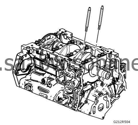
7.
|
Use the
EN 46121
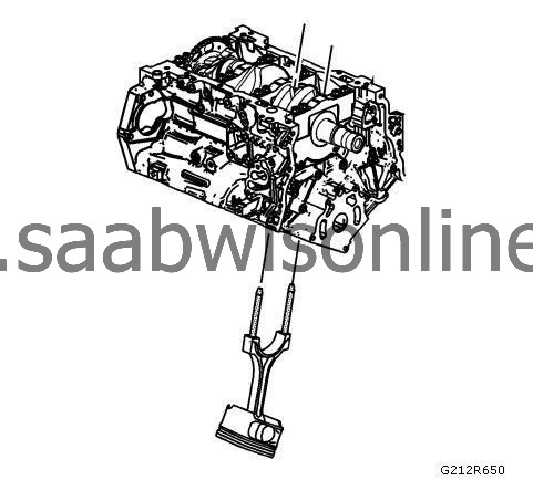
tool set and push the cylinder and connecting rod up through the upper end of the cylinder. Do NOT scratch the crankshaft journal or cylinder wall, and do NOT damage the oil nozzles while removing the cylinder and connecting rod.
|
|
8.
|
Remove the
EN 46121
set from the connecting rod bolt holes.
|
|
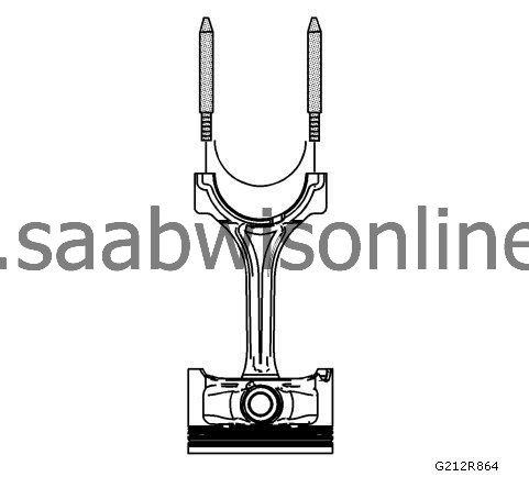
9.
|
Remove the upper connecting rod bearing from the connecting rod.
|
|
10.
|
Remove the lower connecting rod bearing from the connecting rod cap.
|
|
11.
|
Reattach the connecting rod cap to the connecting rod to prevent damage to their mating surfaces. The cap and rod are a matched set and must be kept together.
|
