PRE-RELEASE
Front Compartment Side Rail Sectioning
| Front Compartment Side Rail Sectioning |
| Removal Procedure |
Refer to Approved Equipment for Collision Repair Warning .
Refer to Collision Sectioning Warning .
Refer to Glass and Sheet Metal Handling Warning .
| 1. |
Disable the SIR system. Refer to
SIR Disabling and Enabling
.
|
|
| 2. |
Disconnect the negative battery cable. Refer to
Battery Negative Cable Disconnection and Connection
.
|
|
| 3. |
Remove the front compartment upper side rail. Refer to
Front Compartment Upper Side Rail Replacement
.
|
|
| 4. |
Remove the headlamp mount panel. Refer to
Headlamp Mount Panel Replacement
.
|
|
| 5. |
Remove the front wheelhouse panel brace - inner.
|
|
| 6. |
Remove the front wheelhouse. Refer to
Front Wheelhouse Panel Replacement
.
|
|
| 7. |
Visually inspect the damage. Repair as much of the damage as possible.
|
|
| 8. |
Remove the sealers and anti-corrosion materials from the repair area, as necessary. Refer to
Anti-Corrosion Treatment and Repair (Base)
Anti-Corrosion Treatment and Repair (Corrosion Protection)
.
|
|
| 9. |
Locate and mark all the necessary factory welds of the front compartment side rail (1, 2). 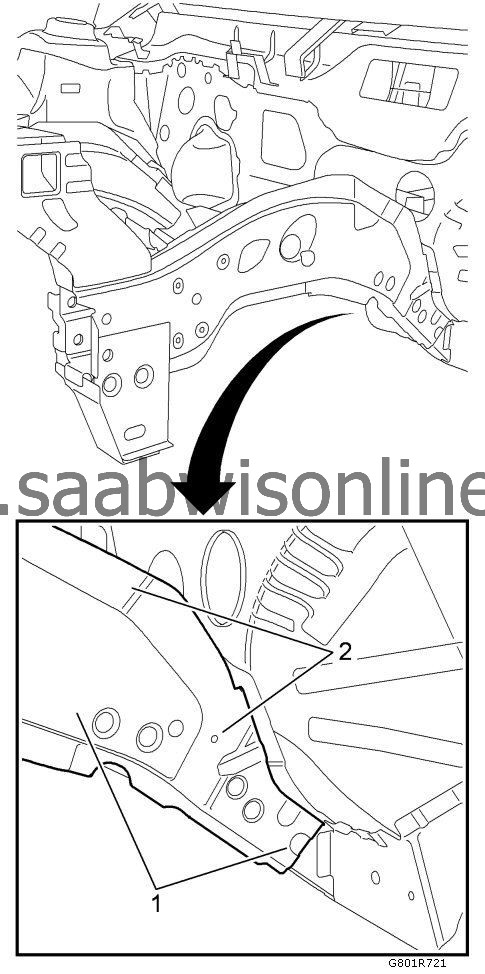
|
|||||||
| 10. |
Drill out all of the necessary factory welds.
|
|
| 11. |
Make a cut-out in the area (1) at the front compartment front outer side rail. 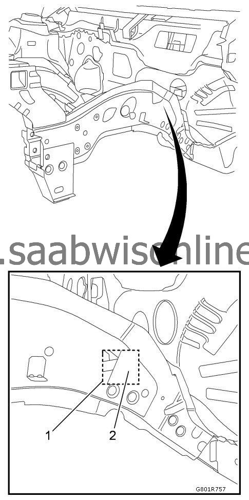
|
|||||||
| 12. |
Drill out the factory weld spot (2).
|
|
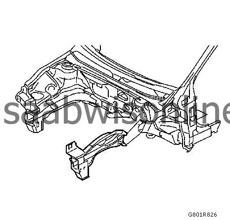
| 13. |
Remove the structural adhesive and the anti-corrosion materials from the repair area (1) with the aid of a hot air gun. 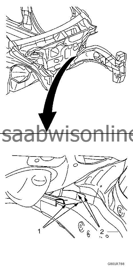
|
|||||||
| 14. |
Locate and mark all the necessary factory welds of the front compartment side rail (2).
|
|
| 15. |
Drill out the necessary factory welds (2).
|
|
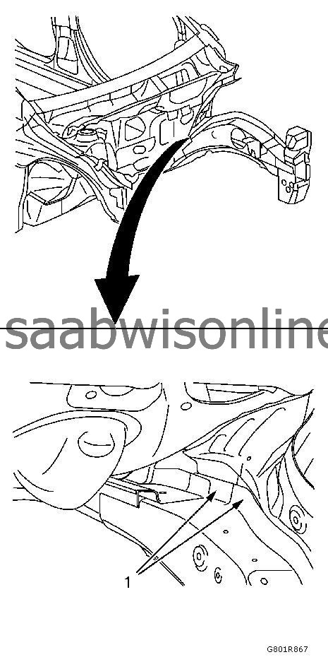
| 16. |
Locate and mark all the necessary factory welds of the front compartment front rail. 
|
|||||||
| 17. |
Drill out the necessary factory welds (1).
|
|
| 18. |
Remove the damaged front compartment side rail.
|
|
| Installation Procedure |
| 1. |
Prepare front compartment rear side rail in the area (1).
Specification2 x slots (6 x 20 mm / 0.2 x 0.8 in)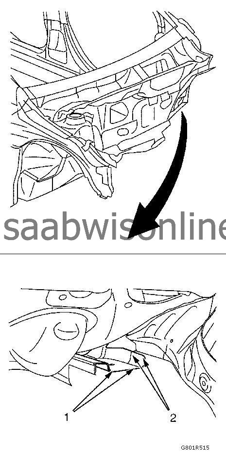
|
|
| 2. |
Clean and prepare the attaching surfaces for welding.
|
|
| 3. |
Apply bodywork repair through structural adhesive to body (2). Refer to
Structural Adhesive Body Repairs
.
|
|
| 4. |
Prepare front compartment rear side rail in the area (1).
Specification1 x slot (8 x 24 mm / 0.3 x 0.9 in)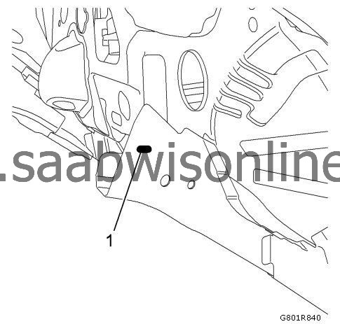
|
|
| 5. |
Prepare new front compartment side rail in the area (1).
Specification8 x slots (8 x 24 mm / 0.3 x 0.9 in)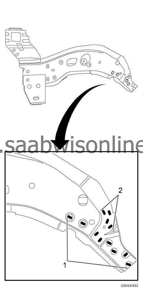
|
|
| 6. |
Prepare new front compartment side rail in the area (1).
Specification4 x slots (8 x 24 mm / 0.3 x 0.9 in) |
|
| 7. |
Prepare new front compartment side rail in the area (1).
Specification8 x slots (8 x 24 mm / 0.3 x 0.9 in)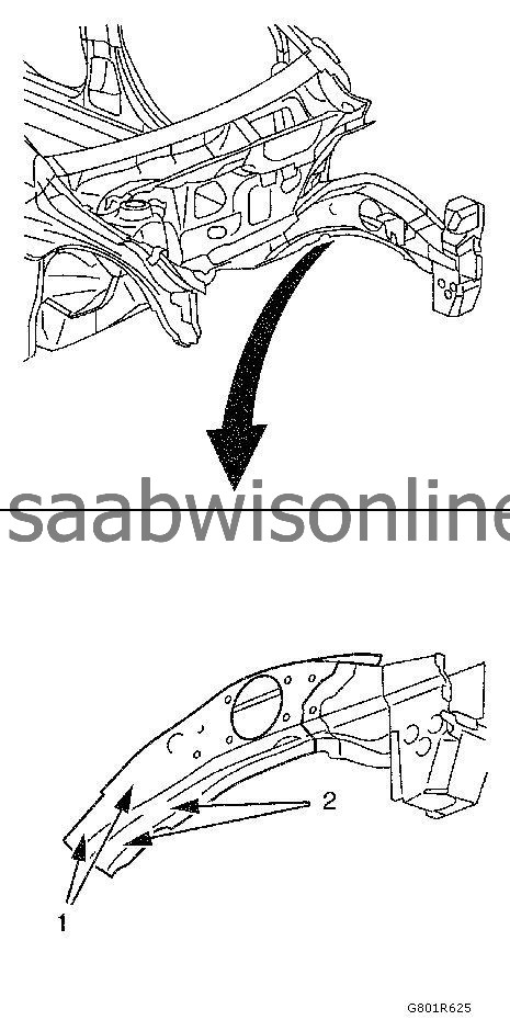
|
|
| 8. |
Prepare new front compartment side rail in the area (2).
Specification3 x slots (8 x 24 mm / 0.3 x 0.9 in) |
|
| 9. |
Clean and prepare the attaching surfaces for welding.
|
|
| 10. |
Apply bodywork repair through structural adhesive to body. Refer to
Structural Adhesive Body Repairs
.
|
|
| 11. |
Position the front compartment side rail on the vehicle.
|
|
| 12. |
Verify the fit of the front compartment side rail.
|
|
| 13. |
Clamp the front compartment side rail into position.
|
|
| 14. |
MIG-braze the front compartment side rail in the area (1).
|
|||||||
| 15. |
Spot weld (2) the front compartment side rail accordingly.
|
|
| 16. |
MIG-braze full seam (1) interrupted 30 mm (1.2 in) . 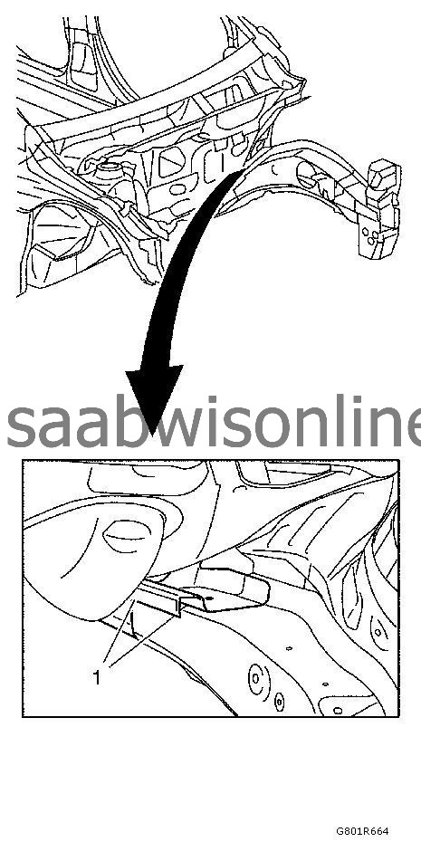
|
|||||||
| 17. |
MIG-braze the front compartment front rail in the areas (1, 2). 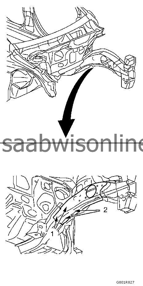
|
|||||||
| 18. |
Spot weld (1) the front compartment side rail accordingly.
|
|
| 19. |
MIG-braze the front compartment side rail in the areas (1). 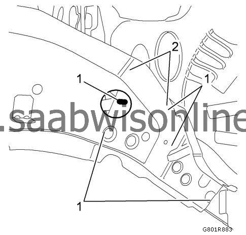
|
|||||||
| 20. |
Spot weld (2) the body rear end panel accordingly.
|
|
| 21. |
MIG-braze full seam (1) interrupted 30 mm (1.2 in) . 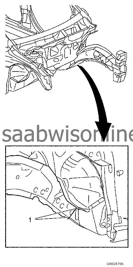
|
|||||||
| 22. |
Apply the sealers and anti-corrosion materials to the repair area, as necessary. Refer to
Anti-Corrosion Treatment and Repair (Base)
Anti-Corrosion Treatment and Repair (Corrosion Protection)
.
|
|
| 23. |
Install the front compartment upper side rail. Refer to
Front Compartment Upper Side Rail Replacement
.
|
|
| 24. |
Install the headlamp mount panel. Refer to
Headlamp Mount Panel Replacement
.
|
|
| 25. |
Install the front wheelhouse panel brace - inner.
|
|
| 26. |
Install the front wheelhouse. Refer to
Front Wheelhouse Panel Replacement
.
|
|
| 27. |
Install the negative battery cable. Refer to
Battery Negative Cable Disconnection and Connection
.
|
|
| 28. |
Enable the SIR system. Refer to
SIR Disabling and Enabling
.
|
|
