PRE-RELEASE
Rocker Outer Panel Reinforcement Replacement (Front)
| Rocker Outer Panel Reinforcement Replacement (Front) |
| Removal Procedure |
Refer to Approved Equipment for Collision Repair Warning .
Refer to Collision Sectioning Warning .
Refer to Glass and Sheet Metal Handling Warning .
| 1. |
Disable the SIR system. Refer to
SIR Disabling and Enabling
.
|
|
| 2. |
Disconnect the negative battery cable. Refer to
Battery Negative Cable Disconnection and Connection
.
|
|
| 3. |
Visually inspect the damage. Repair as much of the damage as possible.
|
|
| 4. |
Remove the rocker panel (center). Refer to
Rocker Panel Replacement (Rear)
Rocker Panel Replacement (Front)
Rocker Panel Replacement (Center)
Rocker Panel Replacement (Complete)
.
|
|
| 5. |
Remove the rocker panel (front). Refer to
Rocker Panel Replacement (Rear)
Rocker Panel Replacement (Front)
Rocker Panel Replacement (Center)
Rocker Panel Replacement (Complete)
.
|
|
| 6. |
Create a cut line on the rocker outer panel reinforcement (front) in the area (1). 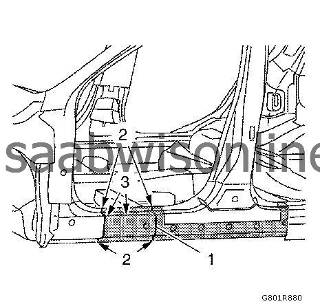
|
|||||||
| 7. |
Locate and drill out all of the necessary factory welds on the rocker outer panel reinforcement (front) (2), (3).
|
|
| 8. |
Remove the damaged the rocker outer panel reinforcement (front) (1).
|
|
| Installation Procedure |
| 1. |
Prepare the new rocker outer panel reinforcement (front).
|
|
| 2. |
Cut (1) the new rocker outer panel reinforcement (front) in corresponding to the fit of the original panel. The sectioning joint should be trimmed to allow min. 1 times the metal thickness at the sectioning joint.
|
|
| 3. |
Prepare the body in the area (2).
4x slots 6 x 20 mm (0.2 x 0.8 in) |
|
| 4. |
Prepare the body in the area (1).
1x slot 8 x 24 mm (0.3 x 0.9 in) 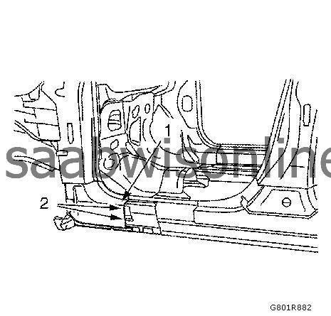
|
|
| 5. |
Prepare the body in the area (2).
5x slots 8 x 24 mm (0.3 x 0.9 in) |
|
| 6. |
Clean and prepare the attaching surfaces for welding. 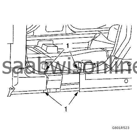
|
|||||||
| 7. |
Apply bodywork repair through structural adhesive to body (1). Refer to
Structural Adhesive Body Repairs
.
|
|
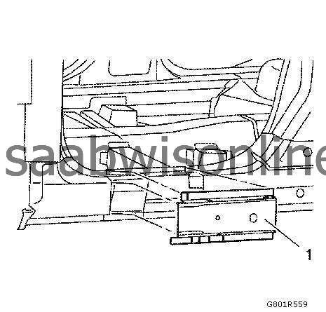
| 8. |
Position the new rocker outer panel reinforcement (front) (1) on the vehicle.
|
|
| 9. |
Verify the fit of the new rocker outer panel reinforcement (front) (1).
|
|
| 10. |
Clamp the new rocker outer panel reinforcement (front) (1) into position.
|
|
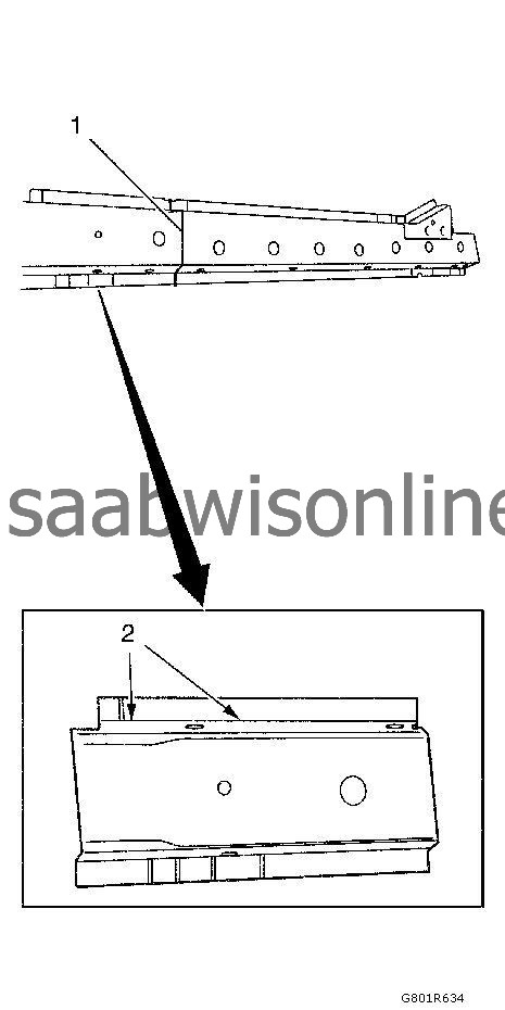
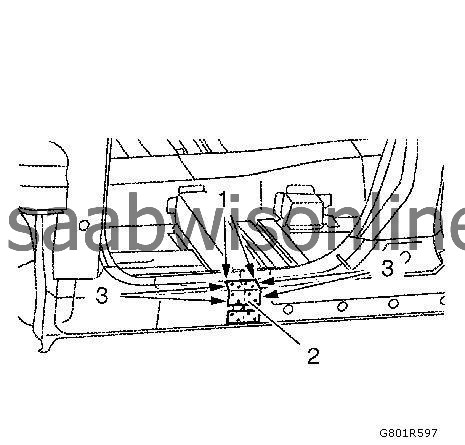
| 11. |
MIG-braze (1) the rocker outer panel reinforcement (front). 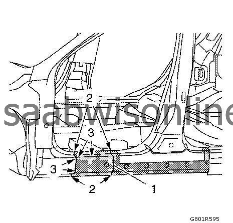
|
|||||||
| 12. |
Spot weld (2) the rocker outer panel reinforcement (front) accordingly.
|
|
| 13. |
MIG-braze (3) the slots on the rocker outer panel reinforcement (front).
|
|
| 14. |
Grind MIG-brazed seams.
|
|
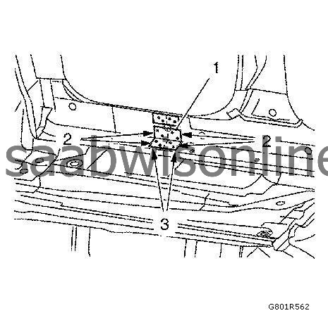
| 15. |
Cut out a
70 mm / 2.8 in
(1) backing plate (2) from an unused area of the service part.
|
|
| 16. |
Drill fastening holes (3) for high strength rivets.
8 holes 6.8 mm / 0.28 in |
|
| 17. |
Rivet the backing plate (3) on the rocker outer panel reinforcement (rear).
|
|
| 18. |
Cut out a
130 mm / 5.1 in
(3) backing plate (1) from an unused area of the service part.
|
|
| 19. |
Drill fastening holes (2) for high strength rivets.
8 holes 6.8 mm / 0.28 in |
|
| 20. |
Rivet the backing plate (2) on the rocker outer panel reinforcement (front).
|
|
| 21. |
Install the rocker panel (center). Refer to
Rocker Panel Replacement (Rear)
Rocker Panel Replacement (Front)
Rocker Panel Replacement (Center)
Rocker Panel Replacement (Complete)
.
|
|
| 22. |
Install the rocker panel (front). Refer to
Rocker Panel Replacement (Rear)
Rocker Panel Replacement (Front)
Rocker Panel Replacement (Center)
Rocker Panel Replacement (Complete)
.
|
|
| 23. |
Apply the sealers and anti-corrosion materials to the repair area, as necessary. Refer to
Anti-Corrosion Treatment and Repair (Base)
Anti-Corrosion Treatment and Repair (Corrosion Protection)
.
|
|
| 24. |
Connect the negative battery cable. Refer to
Battery Negative Cable Disconnection and Connection
.
|
|
| 25. |
Enable the SIR system. Refer to
SIR Disabling and Enabling
.
|
|
