PRE-RELEASE
Windshield Replacement
| Windshield Replacement |
Special Tools
| • |
BO-641
Suction Holder
|
|
| • |
BO-46974
Glass Removal System
|
|
For equivalent regional tools, refer to Special Tools .
|
|||||||
 Warning
| Note | ||
|
The following document describes the procedure for removing the windshield using BO-46974 glass removal system. As a supplement to the existing video VT 54, concise steps will be shown for removing the windshield without destroying it. With the introduction of BO-46974 glass removal system , the conventional glass removing methods are no longer used. |
Position the vehicle on level ground and move the front wheels to the straight-ahead position.
BO-46974 glass removal system is recommended for removing glass without destroying it. Further information can be found in video VT 54.
Before cutting out a stationary window, apply a double layer of masking tape around the perimeter of the painted surfaces.
| Removal Procedure |
| 1. |
Open hood.
|
|
| 2. |
Disconnect the negative battery cable. Refer to
Battery Negative Cable Disconnection and Connection
.
|
|
| 3. |
Remove the plenum water deflector. Refer to
Plenum Water Deflector Replacement
.
|
|
| 4. |
Remove the windshield pillar garnish molding. Refer to
Windshield Side Garnish Molding Replacement
.
|
|
| 5. |
Remove the inside rearview mirror. Refer to
Inside Rearview Mirror Replacement
.
|
|
| 6. |
Remove the front view camera, if equipped. Refer to
Front View Camera Replacement (Object Lens Cleaning)
Front View Camera Replacement (Base)
.
|
|
| 7. |
Remove the windshield outside moisture sensor, if equipped. Refer to
Windshield Outside Moisture and Headlamp Automatic Control Ambient Light Sensor Replacement
.
|
|
| 8. |
Remove lower windshield trim strip.
Remove from guide. 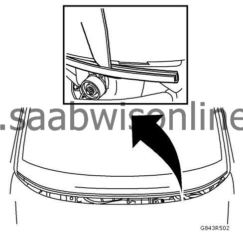
|
|
| 9. |
Cut the cutting wire to length. Unroll 6 m (19.68 ft) of cutting wire from the roll of wire. 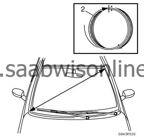
|
|||||||||||||
| 10. |
Insert awl through the adhesive bed. 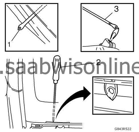
|
|||||||
| • |
Insert the awl (2) (by applying pressure and making slight movements parallel with the adhesive bed).
|
| • |
To make insertion with the awl easier, heat the tip (3) of the awl.
|
| 11. |
Attach cutting wire to the awl. 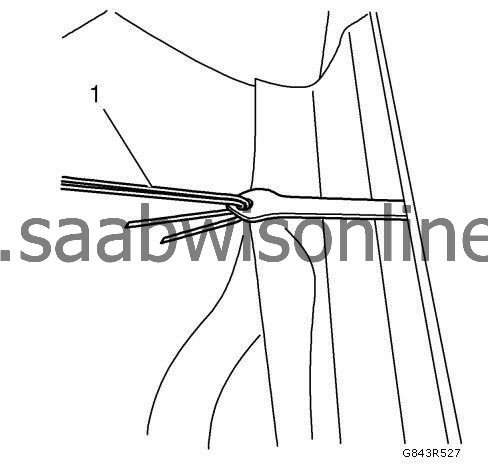
|
|||||||
| • |
Thread the cutting wire (1) through the hole of the awl.
|
| • |
Bend over the cutting wire.
|
| 12. |
Pull the awl and cutting wire into the vehicle. Pull the cutting wire with awl. 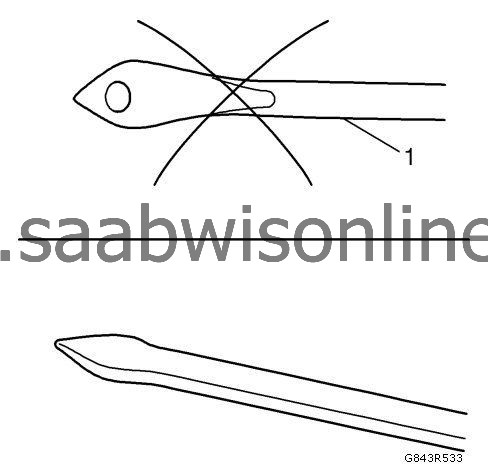
|
|||||||||||||
| 13. |
Lay wire below windshield all round. 
|
|||||||
| 14. |
Position winches in the vehicle. 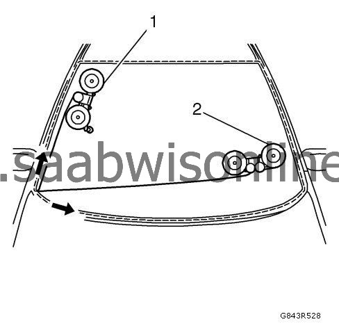
|
|||||||||||||
| • |
Position the winch with one winding head (1) on the right-hand side of the windshield.
|
| • |
Position the winch with two winding heads (2) in the lower left-hand area of the windshield.
|
| • |
Attach 2x cutting wire to winch.
|
| 15. |
Cut out windshield.
|
|
| • |
Use plastic plate to protect instrument panel padding.
|
| • |
Cut out the windshield using the winch and two winding heads until the cutting wire is level with the winding head.
|
| • |
Arrow shows the path taken by the cutting wire.
|
| 16. |
Cut out windshield.
|
|
| • |
Use retainers to protect the A-pillar.
|
| • |
Cut out the windshield using the winch and one winding head until the cutting wire is level with the winding head.
|
| • |
Arrow shows the path taken by the cutting wire.
|
| 17. |
Position winch with one winding head (1) in the vehicle. 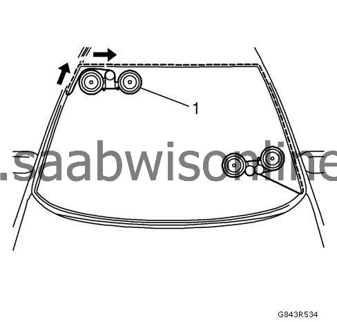
|
|||||||||||||
| • |
Attach roof frame in the top right-hand area.
|
| • |
Insert transfer ratchet and pre-tension cutting wire.
|
| 18. |
Cut out windshield.
|
|
| • |
Cut out the windshield using the winch and one winding head until the cutting wire is level with the winding head.
|
| • |
Arrow shows the path taken by the cutting wire.
|
| 19. |
Position winch with one winding head (1) in the vehicle. 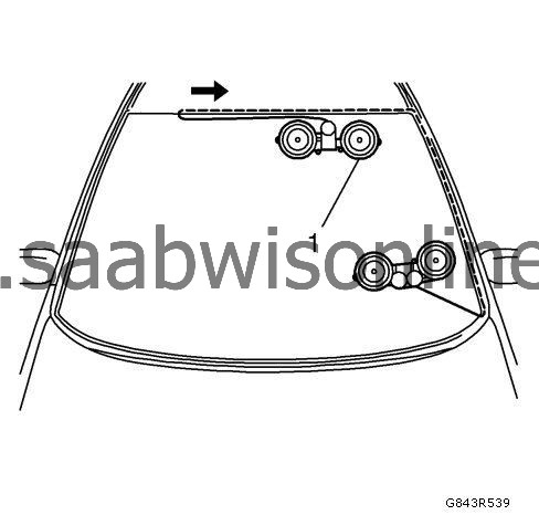
|
|||||||||||||
| • |
Attach roof frame in the left area.
|
| • |
Insert transfer ratchet and pre-tension cutting wire.
|
| 20. |
Cut out windshield.
|
|
| • |
Cut out the windshield using the winch and one winding head until the cutting wire is level with the winding head.
|
| • |
Arrow shows the path taken by the cutting wire.
|
| 21. |
Position winch with one winding head (1) in the vehicle. 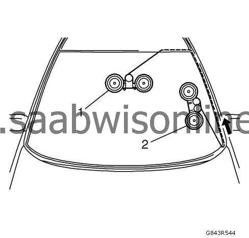
|
|||||||||||||
| • |
Attach in the centre area of the windshield.
|
| • |
Insert transfer ratchet and pre-tension cutting wire.
|
| 22. |
Position winch with two winding heads (2) in the vehicle.
|
|
| • |
Attach in the lower left area of the A-pillar.
|
| • |
Insert transfer ratchet and pre-tension cutting wire.
|
| 23. |
Cut out windshield.
|
|
| • |
Cut out the windshield using the winch and two winding heads until the cutting wire is level with the winding head.
|
| • |
Arrow shows the path taken by the cutting wire.
|
| 24. |
Position winch with two winding heads (1) in the vehicle. 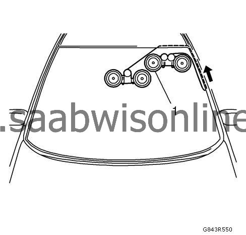
|
|||||||||||||
| • |
Attach roof frame in the left area.
|
| • |
Insert transfer ratchet and pre-tension cutting wire.
|
| 25. |
Cut out windshield.
|
|
| • |
Cut out the windshield until the cutting wire is level with the winch.
|
| • |
Arrow shows the path taken by the cutting wire.
|
| 26. |
Position winch with two winding heads (1) in the vehicle. 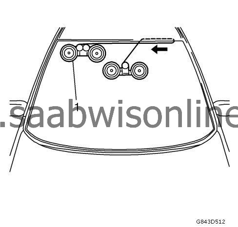
|
|||||||||||||||||||
| • |
Attach roof frame in the right-hand area.
|
| • |
Insert transfer ratchet and pre-tension cutting wire.
|
| 27. |
Cut out windshield.
|
|
| • |
Cut out the windshield until the cutting wire has cut through the adhesive bead completely.
|
| • |
Arrow shows the path taken by the cutting wire.
|
| 28. |
Remove both cutting tools.
|
|
| 29. |
Fit
BO-641
suction holder.
|
|
| 30. |
Remove windshield.
|
|
| 31. |
Cut adhesive bead on the vehicle.
Cut the adhesive bead all round using the knife supplied (1) to around 1 mm (0.04 in) thickness. 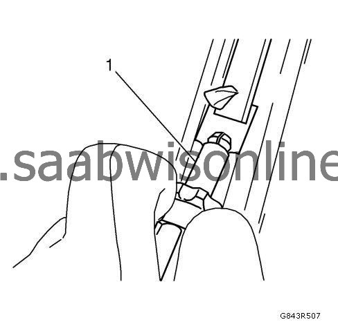
|
|
| 32. |
Repair any paint damage.
Using a touch-up pen to match the color of the vehicle, repair any paint damage. |
|
| 33. |
Cut adhesive bead on the rear windshield.
Cut the adhesive bead all round using the knife supplied to around 1 mm (0.04 in) thickness. |
|
| Installation Procedure |
| 1. |
Apply primer. |
|||||||
| 2. |
Apply adhesive bead.
Cut into the tip of the cartridge in such a way that a bead of adhesive approximately 13 mm (0.5 in) thick is produced. 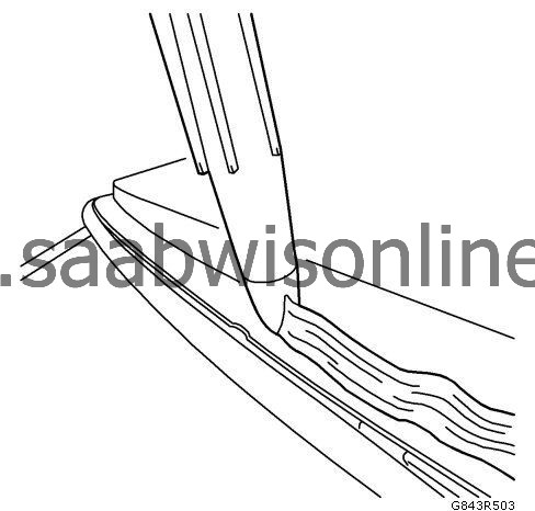
|
|
| 3. |
Install windshield into the opening.
|
|
| • |
Second mechanic required.
|
| • |
Insert windshield with
BO-641
suction holder.
|
| • |
Position using fibre tape.
|
| 4. |
Remove
BO-641
suction holder.
|
|
| 5. |
Install lower windshield trim strip.
|
|
| 6. |
Install the plenum water deflector. Refer to
Plenum Water Deflector Replacement
.
|
|
| 7. |
Install the windshield pillar garnish molding. Refer to
Windshield Side Garnish Molding Replacement
.
|
|
| 8. |
Install the inside rearview mirror. Refer to
Inside Rearview Mirror Replacement
.
|
|
| 9. |
Install the front view camera, if equipped. Refer to
Front View Camera Replacement (Object Lens Cleaning)
Front View Camera Replacement (Base)
.
|
|
| 10. |
Install the windshield outside moisture sensor, if equipped. Refer to
Windshield Outside Moisture and Headlamp Automatic Control Ambient Light Sensor Replacement
.
|
|
| 11. |
Connect the negative battery cable. Refer to
Battery Negative Cable Disconnection and Connection
.
|
|
| 12. |
Close the hood.
|
|
