Check the Shift-lock
Symptom: The selector lever cannot be moved away from position P.
Fault symptoms
The selector lever cannot be moved away from position P.
Diagnostic procedure
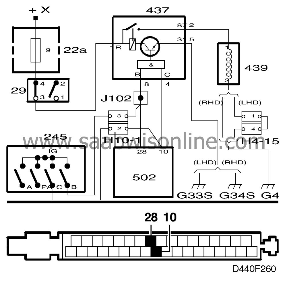
1 Check the relay's connection to ground
|
-
|
Remove the shift-lock relay, mounted in the main fuse box in the dashboard.
|
|
-
|
Check the relay's connection to ground and rectify it if necessary.
|
|
-
|
Connect a voltmeter to pin 31 of the relay socket and battery negative (B-). The reading obtained should be less than 0.1 V.
|
Is the voltage reading OK?
Continue with step 2.
Check and repair or replace the lead between pin 31 of the relay socket and grounding point G34S (RHD) or G33S (LHD). Then proceed to point 6.
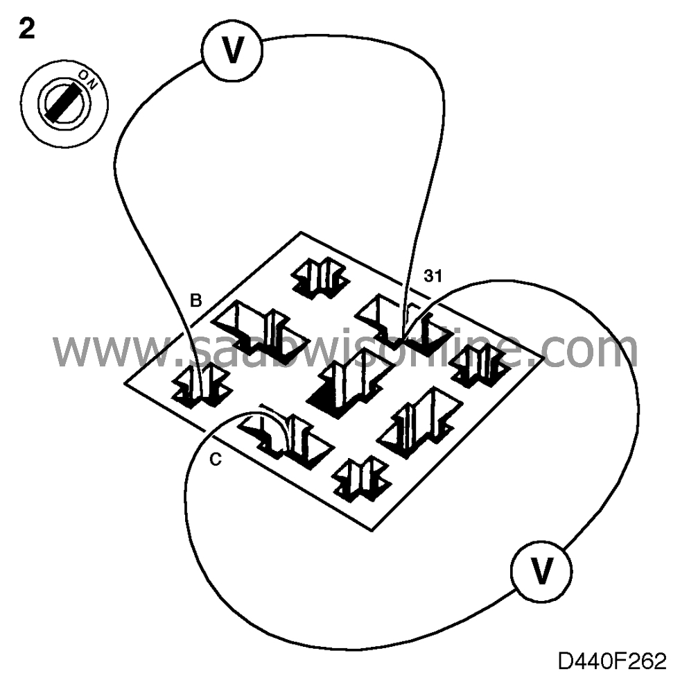
2 Check the relay's signal inputs
|
-
|
Check and, if necessary, rectify the relay's inputs from the gear selector position sensor.
|
|
-
|
With the ignition switch turned to the ON position, connect a voltmeter to the relay socket across • pin B - pin 31 • pin C - pin 31 and move the selector lever through all gear positions. Nominal voltage readings are as in the following table:
|
|
pin B - pin 31
|
pin C - pin 31
|
P
|
< 0.5 V
|
< 0.5 V
|
R
|
12 V
|
< 0.5 V
|
N
|
12 V
|
< 0.5 V
|
D
|
12 V
|
12 V
|
3
|
12 V
|
12 V
|
2
|
< 0.5 V
|
12 V
|
1
|
< 0.5 V
|
12 V
|
A fault in connections B and C can generate diagnostic trouble code P0705. The CHECK GEARBOX lamp is on and the system's emergency operation program (limp home mode) has been activated.
Are the voltage readings OK?
Continue with step 3.
Check and, if necessary, rectify the wiring harness between pins B and C of the relay socket and contacts B and C of the gear selector position sensor. If the wiring harness is OK, the gear selector position sensor will have to be adjusted, see
 . Then proceed to step 6.
3 Check the relay's input from the brake light switch.
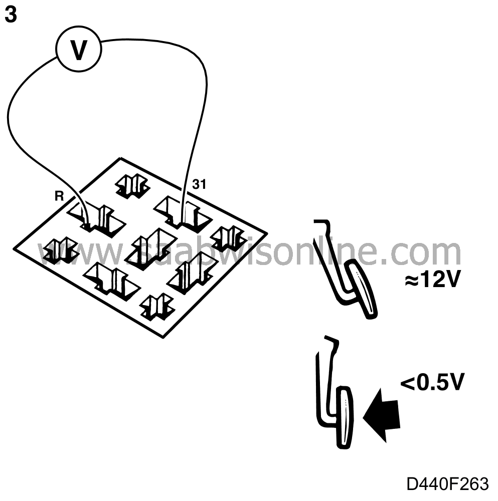
With the ignition switch in the ON position, connect a voltmeter to the relay socket across pins R and 31. Depress the brake pedal. With the brake pedal not depressed, a reading of battery positive (B+) should be obtained. With the brake pedal depressed, a reading of less than 0.5 V should be obtained.
Are the readings correct?
Continue with point 4.
Check - that fuse 9 is intact and supplied with power, using a test lamp. the brake light switch. It might have to be adjusted or changed. - the wiring and proceed to point 6.
4 Check the operation of the lifting electromagnet
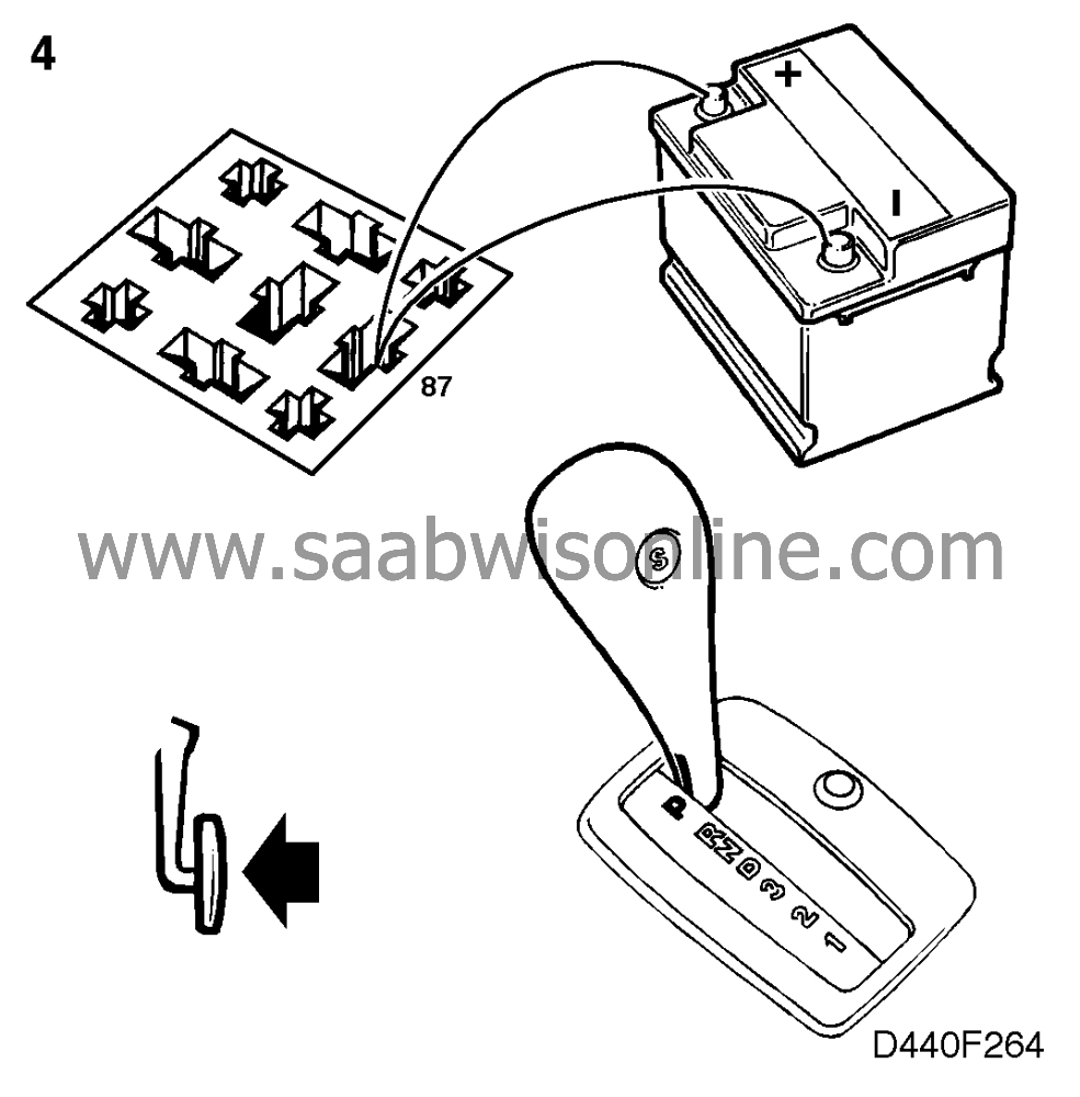
Connect battery positive (B+) and battery negative (B-) or ground alternately to pin 87 of the relay socket. Battery positive (B+) should activate the lifting electromagnet and battery negative (B-) or ground should cause it to release.
Does the electromagnet work?
Change the shift-lock relay and proceed to point 6.
Continue with point 5.
5 Check the lifting electromagnet's wiring

|
-
|
Check and, if necessary, rectify the lifting electromagnet and associated wiring. The lifting electromagnet is located in the selector lever housing.
|
|
-
|
Unplug the lifting electromagnet's connector.
|
|
-
|
Connect a voltmeter to the female connector across • pin 2 and battery negative (B-). Should be less than 0.1 V. • pins 1 and 2. Should be
»
B+ (battery positive) when the brake pedal is not depressed and less than 0.5 V when it is depressed.
|
Are the readings correct?
Change the lifting electromagnet and continue with point 6.
Change the shift-lock relay and proceed to point 6.
6 Final check
Check whether the fault symptom persists.
Does the fault symptom persist?
Continue with “Before changing a control module”, see 4. Automatic Transmission OBD II, Adjustment/replacement
The remedial action taken was correct.
