Cleaning and checking of cylinder head A20NFT/LHU)
|
|
Cleaning and checking of cylinder head A20NFT/LHU)
|
Special tools
|
•
|
EN-28410
Removal tool for gaskets
|
|
•
|
J 7872
Dial indicator with magnetic base
|
|
•
|
J 22738-B
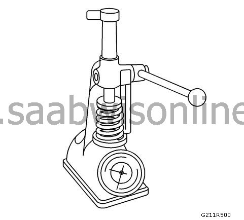
Valve spring tester
|
|
Cleaning and checking of valves
|
|
1.
|
|
Note
|
|
Do not use a steel brush on any part of the valve stem.
|
|
Note
|
|
Do not grind or renovate the intake valve. If the intake valve is not compliant with the specification, replace the valve.
|
Clean the valves to remove combustion residues, oil and paint. Use a steel brush with soft bristles to remove all carbon deposits from the valve head. Veneer can be removed by immersing the parts in a solvent.
|
|
2.
|
Clean the valve guides.
|
|
3.
|
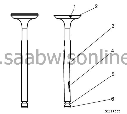
Check the valve spindle for pitting or wear (4).
|
|
4.
|
Check the groove for the valve lug for cuts and wear (5). Replace the valve if if has been cut or is worn.
|
|
5.
|
Check the contact surface of the valve against the seat for burns or cracks (1). If pieces have broken off, check the corresponding piston and cylinder head for damage.
|
|
6.
|
Check the valve stem for burrs and cracks. Burrs and small cracks can be removed with an oilstone.
|
|
7.
|
Check that the valve stem is straight (3) and that the valve head is not bent or damaged using a V-block. Bent or damaged valves must be replaced.
|
|
8.
|
Remove deposits from the contact surface of the valve against the seat. Check the contact surface of the valve against the seat for grooves.
|
|
9.
|
Replace the valve if the contact surface is grooved. Contact surfaces on valves cannot be machined. If the valves are worn or damaged, they must be replaced.
|
|
11.
|
The contact surfaces of the valves can be fine-ground manually.
|
|
12.
|
Replace the valve if the valve top (6) is worn.
|
|
13.
|
If there is no wear, spot corrosion, grooving or distortion, carry out the actions for valve measurement and renovation to check the valve specification. See
Grinding of valve and seat, A20NFT/LHU
.
|
|
1.
|
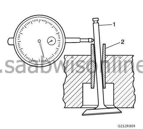
Measure the clearance between the valve stem (1) and the valve guide (2). Excess clearance between the valve stem and the valve guide may cause excessive oil consumption and valve damage. Too little clearance will cause loud, problematic valve function, which will disrupt the even running of the engine unit.
|
|
2.
|
Attach
J 7872
the dial indicator on the cylinder head at the camshaft's protective rail.
|
|
3.
|
Place the dial indicator so that the movement of the valve stem from side to side, across the top cover, causes a direct movement of the indicator leg. The leg of the dial indicator must touch the side of the valve stem immediately above the valve guide.
|
|
4.
|
Lower the valve head approx. 0.064 mm (0.0025 in.) from the valve seat.
|
|
6.
|
|
Note
|
|
Wear on the valve guide 10 mm (0.390 in.) at the bottom of the valve guide is of no significance to normal operation.
|
If the valve clearance is greater than a specified value and a new valve stem with a standard diameter does not give a clearance within the specifications, replace the cylinder head.
|
|
Cleaning and checking of valve springs
|
|
1.
|
Clean the valve springs in solvent.
|
|
2.
|
Dry the valve springs with compressed air.
 Warning
|
|
Wear protective safety glasses.
|
|
|
|
|
|
|
|
3.
|
Check the valve springs for cracked coils or coil ends.
|
|
5.
|
If a low valve spring load is found, the valve springs must be replaced. Do not use spacers to increase the spring load. Use of shims may cause the valve spring to bottom out before the cam nose is in its top position.
|
|
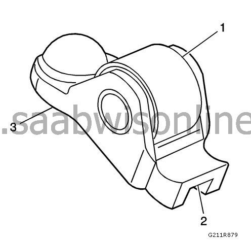
Cleaning and checking of rocker arm
|
|
1.
|
Check tappet roller (1) for the following:
|
|
|
•
|
Large cracks and spot corrosion
|
|
|
•
|
Make sure the roller turns freely
|
|
2.
|
Check the tip of the tappet’s valve (2).
|
|
3.
|
Check the oscillation range (3) for the tappet’s stationary hydraulic lash adjuster (SHLA).
|
|
4.
|
Replace the tappet or tappets where necessary.
|
|
Cleaning and checking the cylinder head and gasket surface
|
|
1.
|
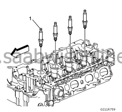
Remove the spark plugs. (1).
|
|
2.
|
Check the cylinder head gasket and mounting surfaces to make sure there are no water leaks, corrosion or compression leaks. If the gasket is broken, you must use the following faults to determine the cause:
|
|
|
•
|
Loose or warped cylinder head
|
|
|
•
|
Tapered tension cotters are missing, not straight or not depressed completely.
|
|
|
•
|
Corrosion in the sealing area around the coolant ducts
|
|
|
•
|
Chips or contamination in the cylinder head screw holes
|
|
|
•
|
The screw holes in the cylinder block are not drilled or threaded sufficiently deeply
|
|
3.
|
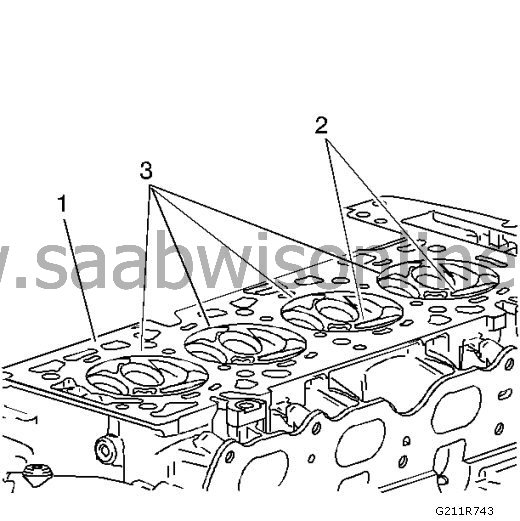
Check the surface of the cylinder head gasket.
|
|
|
•
|
The cylinder head may be reused only if the corrosion area is outside an area 4 mm (0.375 in.) wide around each combustion chamber (1).
|
|
|
•
|
Replace the cylinder head if the area between the valve seats is cracked (2).
|
|
|
•
|
Replace the cylinder head if corrosion is found within an area 4 mm (0.375 in.) wide around each combustion chamber (3).
|
|
4.
|
Clean the cylinder head screws.
|
|
5.
|
|
Note
|
|
Never use a steel brush on a sealing surface for gaskets.
|
Remove the sealant from the rear cover's contact surface with the
EN-28410
removal tool. Take care not to scrape or scratch the sealing surfaces.
|
|
6.
|
Clean the cylinder head screws. Remove all paint, soot and combustion residues until the metal is clean.
|
|
7.
|
Clean the valve guides.
|
|
8.
|
Clean the threaded holes. Use a brush with nylon bristles.
|
|
9.
|
Clear the plug holes of all sealant residues.
|
|
10.
|
Check the cylinder head screws for damaged threads or stretched and damaged heads caused by tools used incorrectly.
|
|
11.
|
Replace all suspect screws.
|
|
12.
|
Check the cylinder head for cracks. Check between the valve seats and in the exhaust ports.
|
|
13.
|
|
Note
|
|
Do not attempt to weld the cylinder head; replace it.
|
Check the cylinder head surface for corrosion, sand inclusions and blisters.
|
|
14.
|
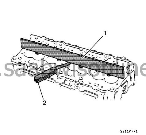
Check the surface evenness of the cylinder head using a straight edge (1) and a feeler gauge (2). Information can be found in
Mechanical engine specifications (A20NFT/LHU)
. If the top cover is outside the specification, replace the top cover. Do not machine the cylinder head in a machine.
|
|
15.
|
Check all threaded holes for damage. Threads can be repaired using thread inserts.
|
|
16.
|
Check the sealing surfaces.
|
|
17.
|
Check the cylinder head plugs (1).
|
|
18.
|
Clean the sealant from the rear cover's contact surface with the
EN-28410
removal tool. Take care not to scrape or scratch the sealing surfaces.
|
|
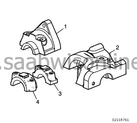
19.
|
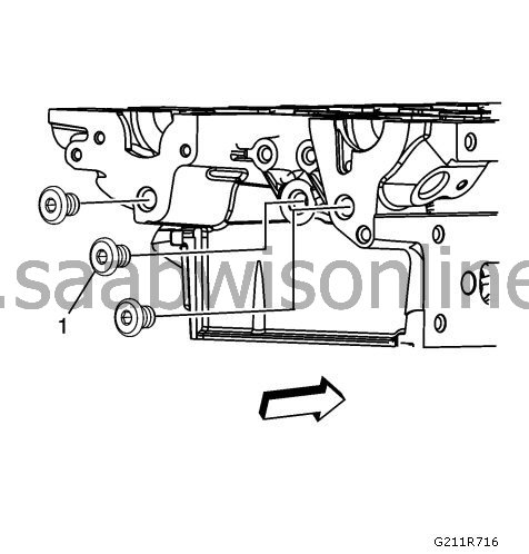
Check the rear bearing covers (1, 2) for the intake and exhaust camshafts for damage.
|
|
20.
|
Check the rear bearing's contact surfaces for damage.
|
|
21.
|
Check the remaining bearing covers (3, 4) for damage.
|
|
22.
|
Fit the spark plugs (1) and tighten to
20 Nm (15 lb ft)
.
|
|
23.
|
Check the hole for the tappet for damage. Make sure that the hole is free from dirt.
|