PRE-RELEASE
Camshaft Replacement - Right Side
| Camshaft Replacement - Right Side |
Special Tools
| • |
EN-46111
Crankshaft Rotation Socket
|
|
| • |
EN-46313
Timing Chain Retention Tool
|
|
For equivalent regional tools, refer to Special Tools .
| Removal Procedure |
| 1. |
Remove the intake manifold. Refer to
Intake Manifold Replacement
.
|
|
| 2. |
Remove the camshaft cover. Refer to
Camshaft Cover Replacement - Right Side (LAU)
Camshaft Cover Replacement - Right Side (LF1 or LFW)
.
|
|
| 3. |
Remove the camshaft sensors. Refer to
Camshaft Position Sensor Replacement - Bank 1 (Right Side) Exhaust
and
Camshaft Position Sensor Replacement - Bank 1 (Right Side) Intake
.
|
|
| 4. |
Remove the intake camshaft position actuator solenoid. Refer to
Camshaft Position Actuator Solenoid Valve Solenoid Replacement - Bank 1 (Right Side) Intake
.
|
|
| 5. |
If equipped with LF1 engine remove the camshaft position actuator . Refer to
Camshaft Position Actuator Replacement - Bank 1 (LF1 or LFW)
.
|
|
| 6. |
If equipped with LAU engine remove the camshaft position actuator. Refer to
Camshaft Position Actuator Replacement - Bank 1 (Right Side) Intake (LAU)
.
|
|
| 7. |
Remove the crankshaft balancer. Refer to
Crankshaft Balancer Replacement
.
|
|
| 8. |
Rotate the crankshaft with the
EN-46111
socket until the camshafts are in a neutral (low tension) position.
The camshaft flats will be parallel with the camshaft cover rail (1). 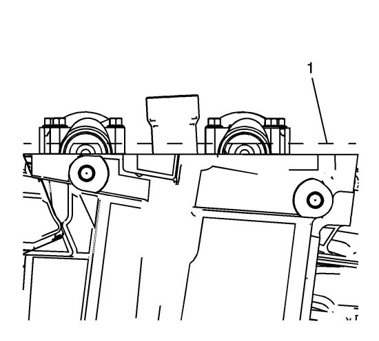
|
|
| 9. |
Refer to
Torque Reaction Against Timing Drive Chain Caution
.
Loosen the camshaft position actuator bolt. 
|
||||||||||
| 10. |
Install the EN-46313 tool in order to retain the timing chain. Firmly tighten the EN-46313 tool nuts . |
|||||||
| 11. |
Mark the timing chain and the respective locations on camshaft position actuators (15-18). 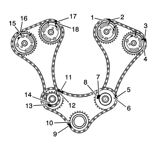
|
|||||||
| 12. |
Remove the camshaft position actuator bolt.
|
|
| 13. |
Remove the camshaft bearing caps and the camshaft. Refer to
Camshaft Removal - Right Side
.
|
|
| Installation Procedure |
| 1. |
Locate the camshafts to the cylinder head and assemble the camshaft actuators to the camshafts.
|
||||||||||
| 2. |
Install the camshafts and the camshaft bearing caps. Refer to
Camshaft Installation - Right Side
.
|
|
| 3. |
Remove the
EN-46313
tool .
|
|
| 4. |
Install the crankshaft balancer. Refer to
Crankshaft Balancer Replacement
.
|
|
| 5. |
Refer to
Torque Reaction Against Timing Drive Chain Caution
.
If equipped with LF1 engine Install the camshaft position actuator . Refer to Camshaft Position Actuator Replacement - Bank 1 (LF1 or LFW) .
|
|||||||
| 6. |
If equipped with LAU engine Install the camshaft position actuator. Refer to
Camshaft Position Actuator Replacement - Bank 1 (Right Side) Intake (LAU)
.
|
|
| 7. |
Install the intake camshaft position actuator solenoid. Refer to
Camshaft Position Actuator Solenoid Valve Solenoid Replacement - Bank 1 (Right Side) Intake
.
|
|
| 8. |
Install the camshaft sensors. Refer to
Camshaft Position Sensor Replacement - Bank 1 (Right Side) Exhaust
and
Camshaft Position Sensor Replacement - Bank 1 (Right Side) Intake
.
|
|
| 9. |
Install the camshaft cover. Refer to
Camshaft Cover Replacement - Right Side (LAU)
Camshaft Cover Replacement - Right Side (LF1 or LFW)
.
|
|
| 10. |
Install the intake manifold. Refer to
Intake Manifold Replacement
.
|
|
