PRE-RELEASE
Turbocharger replacement
| Turbocharger replacement |
| Removal Procedure |
| 1. |
Remove the front bumper fascia. Refer to
Front Bumper Fascia Replacement
.
|
|
| 2. |
Remove the air cleaner outlet duct. Refer to
Air Cleaner Outlet Duct Replacement
.
|
|
| 3. |
Remove the upper intake manifold. Refer to
Upper Intake Manifold Replacement
.
|
|
| 4. |
Remove the catalytic converter. Refer to
Catalytic Converter Replacement (LDK/A20NHT)
Catalytic Converter Replacement (LDK/A20NHT - AWD)
Catalytic Converter Replacement (LBS/A20DTH)
Catalytic Converter Replacement (LAU/A28NER)
.
|
|
| 5. |
Remove the exhaust manifold brace - right side. Refer to Exhaust Manifold Replacement - Right Side (LAU/A28NER) . |
|||||||
| 6. |
Remove the charge air cooler outlet air tube. Refer to
Charge Air Cooler Outlet Air Tube Replacement
.
|
|
| 7. |
Remove the generator. Refer to
Generator Replacement (LDK/A20NHT)
Generator Replacement (Diesel)
Generator Replacement (LAU/A28NER)
.
|
|
| 8. |
Remove the positive crankcase ventilation tube from the oil level indicator tube.
|
|
| 9. |
Remove the secondary air injection inlet pipe. Refer to
Secondary Air Injection Pump Pipe Replacement
.
|
|
| 10. |
Remove the secondary air injection outlet pipe. Refer to
Secondary Air Injection Pump Pipe Replacement
.
|
|
| 11. |
Remove the oil level indicator and tube. Refer to
Oil Level Indicator Tube Replacement
.
|
|
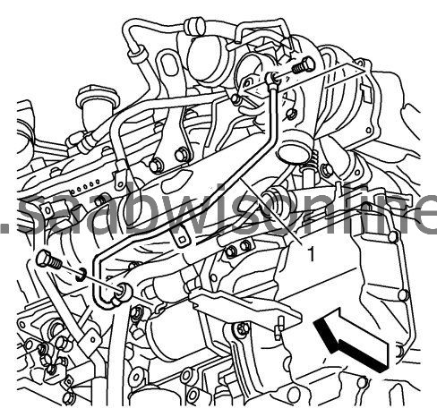
| 12. |
Remove the turbocharger coolant feed pipe (1).
|
|
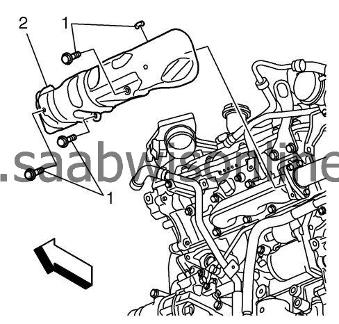
| 13. |
Remove the 4 exhaust front manifold heat shield fasteners (1).
|
|
| 14. |
Remove the exhaust front manifold heat shield (2).
|
|
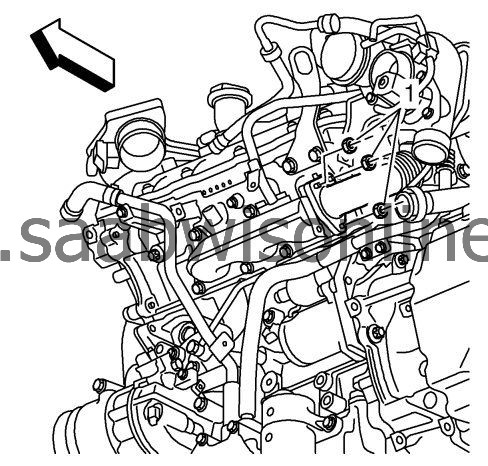
| 15. |
Remove the 3 exhaust manifold brace fasteners (1).
|
|
| 16. |
Remove the exhaust turbocharger inlet pipe fasteners (1).
|
|
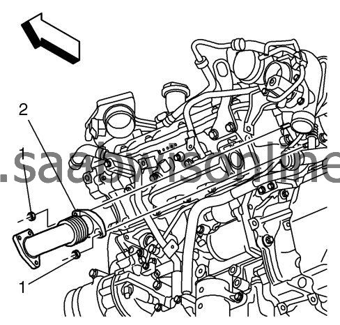
| 17. |
Remove the exhaust turbocharger inlet pipe (2).
|
|
| 18. |
Remove the charge cooler inlet hose. Refer to
Charge Air Cooler Inlet Hose Replacement (LBS/A20DTH)
Charge Air Cooler Inlet Hose Replacement (LAU/A28NER)
.
|
|
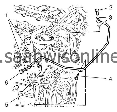
| 19. |
Remove the 2 turbocharger oil feed pipe fittings (2, 6) and gaskets (1, 3).
|
|
| 20. |
Remove the turbocharger oil feed pipe fastener (4).
|
|
| 21. |
Remove the turbocharger oil feed pipe (5).
|
|
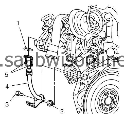
| 22. |
Remove the 2 turbocharger oil return pipe fasteners (5).
|
|
| 23. |
Remove the turbocharger oil return pipe fastener (3).
|
|
| 24. |
Remove the turbocharger oil return pipe (4).
|
|
| 25. |
Remove the turbocharger oil return pipe gasket (1).
|
|
| 26. |
Remove the turbocharger oil return pipe seal (2).
|
|
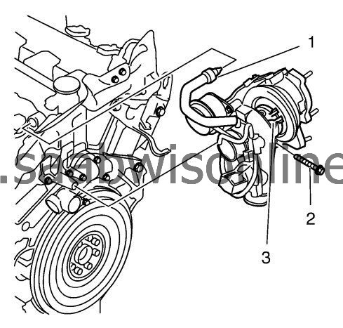
| 27. |
Remove the positive crankcase ventilation tube (1).
|
|
| 28. |
Remove the turbocharger fastener (2).
|
|
| 29. |
Remove the turbocharger (3).
|
|
| Installation Procedure |
| 1. |
Refer to
Fastener Caution
.
Install the turbocharger (3).
|
|
| 2. |
Install the turbocharger bracket (2) and tighten to
65 Nm (48 lb ft)
.
|
|
| 3. |
Install the positive crankcase ventilation tube (1).
|
|
| 4. |
Install the NEW turbocharger oil return pipe seal (2).
|
|
| 5. |
Install the NEW turbocharger oil return pipe gasket (1).
|
|
| 6. |
Install the turbocharger oil return pipe (4).
|
|
| 7. |
Install the 2 turbocharger oil return pipe fasteners (5) and tighten to
14 Nm (11 lb ft)
.
|
|
| 8. |
Install the turbocharger return oil hose bracket (3) and tighten to
65 Nm (48 lb ft)
.
|
|
| 9. |
Install the turbocharger oil feed pipe (5).
|
|
| 10. |
Install the NEW turbocharger oil feed pipe fastener gaskets (1, 3).
|
|
| 11. |
Install the turbocharger oil feed pipe fastener (4).
|
|
| 12. |
Install the 2 turbocharger oil feed pipe fittings (2, 6) and tighten the banjo screws to
30 Nm(22 lb ft)
.
|
|
| 13. |
Install the charge air cooler inlet hose. Refer to
Charge Air Cooler Inlet Hose Replacement (LBS/A20DTH)
Charge Air Cooler Inlet Hose Replacement (LAU/A28NER)
.
|
|
| 14. |
Install a NEW exhaust turbocharger inlet pipe gasket.
|
|
| 15. |
Install the exhaust turbocharger inlet pipe (2).
|
|
| 16. |
Install the turbocharger intake manifold fasteners (1) and tighten to
30 Nm (22 lb ft)
.
|
|
| 17. |
Install the 3 fasteners to the exhaust manifold(1) and tighten to
30 Nm (22 lb ft)
.
|
|
| 18. |
Install the exhaust front manifold heat shield (2).
|
|
| 19. |
Install the 4 exhaust front manifold heat shield fasteners (1) and tighten to
10 Nm (89 lb in)
.
|
|
| 20. |
Install the turbocharger coolant delivery pipe (1) and tighten the M12 to
30 Nm (22 lb ft)
and then the M14 to
35 Nm (26 lb ft)
.
|
|
| 21. |
Install the oil level indicator and tube. Refer to
Oil Level Indicator Tube Replacement
.
|
|
| 22. |
Install the secondary air injection outlet pipe. Refer to
Secondary Air Injection Pump Pipe Replacement
.
|
|
| 23. |
Install the secondary air injection inlet pipe. Refer to
Secondary Air Injection Pump Pipe Replacement
.
|
|
| 24. |
Install the positive crankcase ventilation tube to the oil level indicator tube.
|
|
| 25. |
Install the generator. Refer to
Generator Replacement (LDK/A20NHT)
Generator Replacement (Diesel)
Generator Replacement (LAU/A28NER)
.
|
|
| 26. |
Install the charge air cooler outlet air tube. Refer to
Charge Air Cooler Outlet Air Tube Replacement
.
|
|
| 27. |
Install the exhaust manifold brace - right side. Refer to
Exhaust Manifold Replacement - Right Side (LAU/A28NER)
.
|
|
| 28. |
Install the catalytic converter. Refer to
Catalytic Converter Replacement (LDK/A20NHT)
Catalytic Converter Replacement (LDK/A20NHT - AWD)
Catalytic Converter Replacement (LBS/A20DTH)
Catalytic Converter Replacement (LAU/A28NER)
.
|
|
| 29. |
Install the upper intake manifold. Refer to
Upper Intake Manifold Replacement
.
|
|
| 30. |
Install the air cleaner outlet duct. Refer to
Air Cleaner Outlet Duct Replacement
.
|
|
| 31. |
Install the front bumper fascia. Refer to
Front Bumper Fascia Replacement
.
|
|
