PRE-RELEASE
Engine Replacement
| Engine Replacement |
Special Tools
| • |
CH-807
Closure Plug
|
|
| • |
CH-904
Base Frame
|
|
| • |
CH-49289
Centring Adapter
|
|
| • |
CH-49290
Mounting Engine/Transmission
|
|
| • |
EN-412
Engine Stand
|
|
| Removal Procedure |
| 1. |
Turn the ignition OFF.
|
|
| 2. |
Remove the intermediate steering shaft fastener. Refer to
Intermediate Steering Shaft Replacement
.
|
|
| 3. |
Open hood.
|
|
| 4. |
Evacuate the air conditioning system. Refer to
Refrigerant Recovery and Recharging
.
|
|
| 5. |
Remove the engine control module. Refer to
Engine Control Module Replacement (LLU/A16LET)
.
|
|
| 6. |
Remove the battery tray. Refer to
Battery Tray Replacement (Diesel)
Battery Tray Replacement (LHU/A20NFT)
.
|
|
| 7. |
Raise and support the vehicle. Refer to
Lifting and Jacking the Vehicle
.
|
|
| 8. |
Remove the front wheels. Refer to
Tire and Wheel Removal and Installation
.
|
|
| 9. |
Remove the front bumper fascia. Refer to
Front Bumper Fascia Replacement
.
|
|
| 10. |
Drain the cooling system. Refer to
Cooling System Draining and Filling (LAU/A28NER)
Cooling System Draining and Filling (LBS/A20DTH)
Cooling System Draining and Filling (LHU/A20NFT)
.
|
|
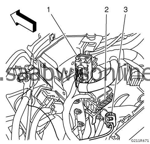
| 11. |
Disconnect the engine wiring harness connectors (1, 2).
|
|
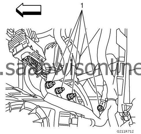
| 12. |
Remove the engine wiring harness ground connectors (1) from the front end upper tie bar support.
|
|
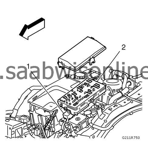
| 13. |
Remove the engine wiring harness (1) from the front compartment fuse block housing (2).
|
|
| 14. |
Remove the wiring harness bracket from the transmission. Disconnect the backup lamp switch electrical connector.
|
|
| 15. |
Position and secure the wiring harness to the engine.
|
|
| 16. |
Remove both coolant hoses from the radiator surge tank. Position and secure the surge hoses to the engine.
|
|
| 17. |
Remove the clutch actuator cylinder hose.
|
|
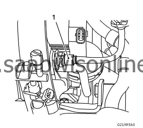
| 18. |
Remove the power brake booster pipe (1) from the intake manifold.
|
|
| 19. |
Remove the manual transmission shift lever cable from the transmission. Refer to
Selector Lever Cable Replacement
.
|
|
| 20. |
Remove the heater inlet hose and the heater outlet hose from the heater core. Refer to
Heater Inlet Hose Replacement (Diesel)
Heater Inlet Hose Replacement (LAU/A28NER)
Heater Inlet Hose Replacement (LLU/A16LET)
Heater Inlet Hose Replacement (LHU/A20NFT)
and
Heater Outlet Hose Replacement (Diesel)
Heater Outlet Hose Replacement (LAU/A28NER)
Heater Outlet Hose Replacement (LLU/A16LET)
Heater Outlet Hose Replacement (LHU/A20NFT)
.
|
|
| 21. |
Relieve the fuel system pressure. Refer to
Fuel Pressure Relief
.
|
|
| 22. |
Disconnect the evaporative emission pipe quick connector. Close the pipe with the
CH-807
closure plug.
|
|
| 23. |
Disconnect the evaporative emission canister purge solenoid valve electrical connector.
|
|
| 24. |
Disconnect the fuel feed pipe and fuel return pipe. Close the pipes with the
CH-807
closure plugs to prevent fuel loss or contamination.
|
|
| 25. |
Remove the air cleaner outlet duct with the air cleaner assembly. Refer to
Air Cleaner Outlet Duct Replacement (LLU/A16LET)
and
Air Cleaner Assembly Replacement (LLU/A16LET)
.
|
|
| 27. |
Raise the vehicle by its full height.
|
|
| 28. |
Remove the front compartment splash shield. Refer to
Front Compartment Splash Shield Replacement
.
|
|
| 29. |
Disconnect both front wheel speed sensor electrical connectors. Position and secure both wiring harnesses to the vehicle. Refer to
Front Wheel Speed Sensor Replacement (GNA)
Front Wheel Speed Sensor Replacement (GNB)
.
|
|
| 30. |
Disconnect the engine coolant fan motor wiring harness connectors.
|
|
| 31. |
Remove exhaust front pipe. Refer to Exhaust Front Pipe Replacement (LBY/A20DTR) Exhaust Front Pipe Replacement (LLU/A16LET) Exhaust Front Pipe Replacement (LBS/A20DTH) Exhaust Front Pipe Replacement (LHU/A20NFT, LAU/A28NER) . |
|||||||
| 32. |
Lower the vehicle by its half height.
|
|
| 33. |
Remove the front wheel drive shaft fasteners. Refer to
Front Wheel Drive Shaft Replacement - Right Side (GNB)
Front Wheel Drive Shaft Replacement - Right Side (Petrol)
and
Front Wheel Drive Shaft Replacement - Left Side (GNA)
Front Wheel Drive Shaft Replacement - Left Side (GNB)
.
|
|
| 34. |
Remove the stabilizer shaft link fasteners. Refer to
Stabilizer Shaft Link Replacement (GNA)
Stabilizer Shaft Link Replacement (GNB)
.
|
|
| 35. |
Remove the steering linkage outer tie rod fasteners. Refer to
Steering Linkage Outer Tie Rod Replacement
.
|
|
| 36. |
Remove both steering knuckles from both front lower control arms. Refer to
Steering Knuckle Replacement (GNA)
Steering Knuckle Replacement (GNB)
.
|
|
| 37. |
Remove both front wheel drive shafts from both front wheel bearings and hubs. Refer to
Front Wheel Bearing and Hub Replacement (GNA)
Front Wheel Bearing and Hub Replacement (GNB)
.
|
|
| 38. |
Raise the vehicle by its full height.
|
|
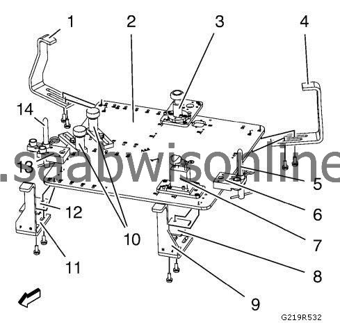
| Prepare the CH-49290 for Mounting Engine |
| 1. |
Install the tool components on the
CH-49290-1
plate (2).
|
|
| • |
CH-49290-16
supporting with
CH-49290-15
plate (3) at position 20 and X.
|
| • |
CH-49290-5
bracket (6) at position 02.
|
| • |
CH-49290-6
pin (5) at position E on the
CH-49290-5
bracket (6).
|
| • |
CH-49290-14
supporting with
CH-49290-12
plate (7) at position 13 and Q.
|
| • |
Two bolts with 2
CH49290-18
supporting (10) at position 32 and position 40.
|
| • |
CH-49290-4
bracket (13) at position 01.
|
| • |
CH-49290-6
pin (14) at position B on the
CH-49290-4
bracket (13).
|
| 2. |
Turn the CH-49290-18 supporting (10), CH-49290-14 supporting (7) and CH-49290-16 supporting (3) downward. |
|||||||
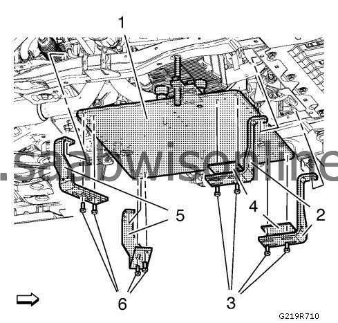
| Install the CH-49290 for Mounting Engine |
| 1. |
Install the
CH-49290
mounting on the
CH-904
frame.
|
|
| 2. |
Raise the
CH-49290
mounting (1) with a jack.
|
|
| 3. |
Install the CH-49290-9 bracket and CH-49290-8 bracket (2) with 2 CH-49290-7 plates (4). |
|||||||
| • |
CH-49290-8
bracket at position G.
|
| • |
CH-49290-9
bracket at position H.
|
| 4. |
Install the 4 bolts (3).
|
|
| 5. |
Install the
CH-49290-10
bracket and
CH-49290-11
bracket (5).
|
|
| • |
CH-49290-10
bracket at position K.
|
| • |
CH-49290-11
bracket at position N.
|
| 6. |
Install the 4 bolts (6).
|
|
| 7. |
Lower the jack with
CH-904
frame and remove it.
|
|
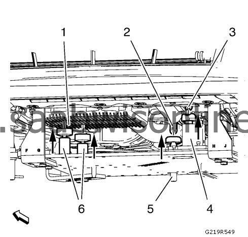
| 8. |
Turn the
CH-49290-14
supporting (4) upwards until it seats solidly at the transmission front mount (3).
|
|
| 9. |
Turn the
CH-49290-16
supporting (5) upwards until it seats solidly at the transmission rear mount (2).
|
|
| 10. |
Turn the 2
CH-49290-18
supporting (6) upwards until it seats solidly at the oil pan (1).
|
|
| Removal Procedure |
| 1. |
Lower the vehicle.
|
|
| 2. |
Remove the engine mount bracket from the engine mount support. Refer to
Engine Mount Replacement
.
|
|
| 3. |
Remove the transmission mount fasteners. Refer to
Transmission Mount Replacement - Left Side
.
|
|
| 4. |
Raise the vehicle by its full height.
|
|
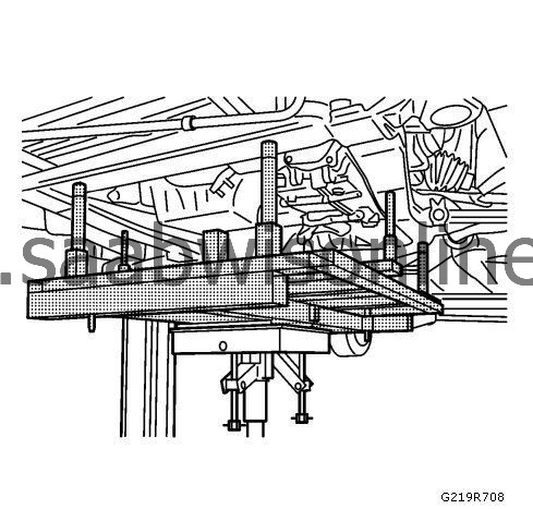
| 5. |
Raise the
CH-904
underframe and
CH-49289
adapter with the hydraulic jack until it contact the frame.
|
|
| 6. |
Check if wheel alignment is required. 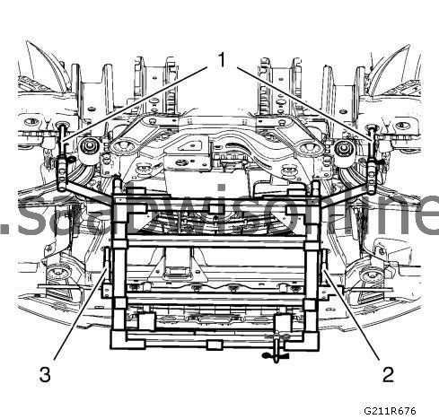
|
|||||||
| • |
Move out position pins (1) and try to insert into underbody holes.
|
| • |
If guide pins can NOT be inserted, the
Wheel Alignment Measurement
is required after installation of drive train frame.
|
| 7. |
Remove the front suspension frame fasteners. Refer to
Drivetrain and Front Suspension Frame Front Crossmember Replacement (GNA)
Drivetrain and Front Suspension Frame Front Crossmember Replacement (GNB)
.
|
|
| 8. |
With the aid of an assistant, lower the table or raise the vehicle to remove the engine, transmission, front frame and front suspension assembly from the vehicle. |
|||||||
| 9. |
Remove the right wheel drive shaft from the transmission. Refer to
Front Wheel Drive Shaft Replacement - Right Side (GNB)
Front Wheel Drive Shaft Replacement - Right Side (Petrol)
.
|
|
| 10. |
Remove the left wheel drive shaft from the transmission. Refer to
Front Wheel Drive Shaft Replacement - Left Side (GNA)
Front Wheel Drive Shaft Replacement - Left Side (GNB)
.
|
|
| 11. |
Vehicles equipped with LLU/A16LET, remove the charge air cooler inlet air hose. Refer to
Charge Air Cooler Inlet Hose Replacement (LAU/A28NER)
Charge Air Cooler Inlet Hose Replacement (LBY/A20DTR)
Charge Air Cooler Inlet Hose Replacement (LLU/A16LET)
Charge Air Cooler Inlet Hose Replacement (LBS/A20DTH)
.
|
|
| 12. |
Vehicles equipped with LLU/A16LET, remove the charge air cooler outlet air hose. Refer to
Charge Air Cooler Outlet Hose Replacement (Diesel)
Charge Air Cooler Outlet Hose Replacement (LAU/A28NER)
Charge Air Cooler Outlet Hose Replacement (LLU/A16LET)
.
|
|
| 13. |
Remove the power steering return hose from the power steering pump. Refer to
Power Steering Return Hose Replacement (L4)
Power Steering Return Hose Replacement (V6)
.
|
|
| 14. |
Remove the power steering pressure pipe/hose from the power steering pump. Refer to
Power Steering Pressure Pipe/Hose Replacement (L4)
Power Steering Pressure Pipe/Hose Replacement (V6)
.
|
|
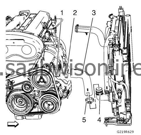
| 15. |
Loosen the radiator outlet hose clamp (2).
|
|
| 16. |
Remove the radiator outlet hose (3) from the water pump (1).
|
|
| 17. |
Loosen the radiator inlet hose clamp (4).

|
|
| 18. |
Remove the radiator inlet hose (3) from the engine coolant thermostat (5).
|
|
| 19. |
Install suitable cables at the 3 engine lift brackets.
|
|
| 20. |
Install a suitable engine lifting device to the cables.
|
|
| 21. |
Extend the engine lifting device until the steel cables are slightly tensioned.
|
|
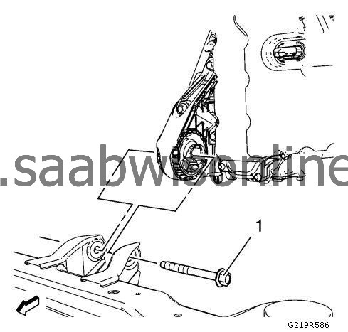
| 22. |
Remove the front transmission mount fastener (1).
|
|
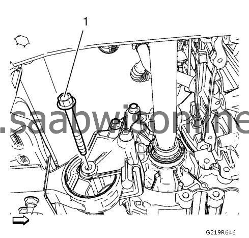
| 23. |
Remove the transmission bracket mount fastener (1).
|
|
| 24. |
Put the engine transmission unit down on a wooden pallet.
|
|
| 25. |
Loosen the 8 transmission bolts and remove 7 of them.
|
|
| 26. |
Remove the last transmission bolt and the transmission. |
|||||||
| 27. |
Install the engine to the
EN-412
engine stand.
|
|
| 28. |
Transfer parts as needed.
|
|
| Installation Procedure |
| 1. |
Remove the engine from the
EN-412
engine stand.
|
|
| 2. |
Put the engine down on a wooden pallet.
|
|
| 3. |
Install the transmission and one transmission bolt. |
|||||||
| 4. |
Install the 7 transmission bolts.
|
|
| 5. |
Tighten the 8 transmission bolts.
|
|
| 6. |
Place the engine transmission unit into the front frame.
|
|
| 7. |
Refer to
Fastener Caution
.
Install the fastener (1) of the transmission mount and tighten up to 100 Nm (74 lb ft) .
|
|
| 8. |
Install the front fastener (1) for the transmission and tighten to
100 Nm (74 lb ft)
.
|
|
| 9. |
Remove the cables from the 3 engine lift brackets.
|
|
| 10. |
Install the radiator inlet hose (3) to the engine coolant thermostat (5).
|
|
| 11. |
Install the radiator inlet hose clamp (4).
|
|
| 12. |
Install the radiator outlet hose (3) to the water pump (1).
|
|
| 13. |
Install the radiator outlet hose clamp (2).
|
|
| 14. |
Install the power steering pressure pipe/hose to the power steering pump. Refer to
Power Steering Pressure Pipe/Hose Replacement (L4)
Power Steering Pressure Pipe/Hose Replacement (V6)
.
|
|
| 15. |
Install the power steering return hose to the power steering pump. Refer to
Power Steering Return Hose Replacement (L4)
Power Steering Return Hose Replacement (V6)
.
|
|
| 16. |
Vehicles equipped with LLU/A16LET, install the charge air cooler outlet air hose. Refer to
Charge Air Cooler Outlet Hose Replacement (Diesel)
Charge Air Cooler Outlet Hose Replacement (LAU/A28NER)
Charge Air Cooler Outlet Hose Replacement (LLU/A16LET)
.
|
|
| 17. |
Vehicles equipped with LLU/A16LET, install the charge air cooler inlet air hose. Refer to
Charge Air Cooler Inlet Hose Replacement (LAU/A28NER)
Charge Air Cooler Inlet Hose Replacement (LBY/A20DTR)
Charge Air Cooler Inlet Hose Replacement (LLU/A16LET)
Charge Air Cooler Inlet Hose Replacement (LBS/A20DTH)
.
|
|
| 18. |
Install the left wheel drive shaft to the transmission. Refer to
Front Wheel Drive Shaft Replacement - Left Side (GNA)
Front Wheel Drive Shaft Replacement - Left Side (GNB)
.
|
|
| 19. |
Install the right wheel drive shaft to the transmission. Refer to
Front Wheel Drive Shaft Replacement - Right Side (GNB)
Front Wheel Drive Shaft Replacement - Right Side (Petrol)
.
|
|
| 20. |
With the aid of an assistant, raise the table or lift the vehicle to install the engine, transmission, front frame and front suspension assembly to the vehicle. |
|||||||
| 21. |
Install the front suspension frame fasteners. Refer to
Drivetrain and Front Suspension Frame Front Crossmember Replacement (GNA)
Drivetrain and Front Suspension Frame Front Crossmember Replacement (GNB)
.
|
|
| 22. |
Insert positioning pins (1).
|
|||||||
| 23. |
Lower the
CH-49289
adapter with the hydraulic jack.
|
|
| 24. |
Lower the vehicle.
|
|
| 25. |
Install the transmission mount fasteners. Refer to
Transmission Mount Replacement - Left Side
.
|
|
| 26. |
Install the engine mount bracket to the engine mount support. Refer to
Engine Mount Replacement
.
|
|
| 27. |
Raise the vehicle by its full height.
|
|
| 28. |
Install the
CH-904
frame with a jack to the
CH-49290
mounting (1).
|
|
| 29. |
Remove the 4 bolts (3).
|
|
| 30. |
Remove the
CH-49290-9
bracket and
CH-49290-8
bracket (2) with 2
CH-49290-7
plates (4).
|
|
| 31. |
Remove the 4 bolts (6).
|
|
| 32. |
Remove the
CH-49290-10
bracket and
CH-49290-11
bracket (5).
|
|
| 33. |
Lower the
CH-49290
mounting and the
CH-904
frame with the jack.
|
|
| 34. |
Lower the vehicle.
|
|
| 35. |
Install both front wheel drive shafts to both front wheel bearings and hubs. Refer to
Front Wheel Bearing and Hub Replacement (GNA)
Front Wheel Bearing and Hub Replacement (GNB)
.
|
|
| 36. |
Install both steering knuckles to both front lower control arms. Refer to
Steering Knuckle Replacement (GNA)
Steering Knuckle Replacement (GNB)
.
|
|
| 37. |
Install the steering linkage outer tie rod fasteners. Refer to
Steering Linkage Outer Tie Rod Replacement
.
|
|
| 38. |
Install the stabilizer shaft link fasteners. Refer to
Stabilizer Shaft Link Replacement (GNA)
Stabilizer Shaft Link Replacement (GNB)
.
|
|
| 39. |
Install the front wheel drive shaft fasteners. Refer to
Front Wheel Drive Shaft Replacement - Right Side (GNB)
Front Wheel Drive Shaft Replacement - Right Side (Petrol)
and
Front Wheel Drive Shaft Replacement - Left Side (GNA)
Front Wheel Drive Shaft Replacement - Left Side (GNB)
.
|
|
| 40. |
Raise the vehicle.
|
|
| 41. |
Install the exhaust front pipe. Refer to
Exhaust Front Pipe Replacement (LBY/A20DTR)
Exhaust Front Pipe Replacement (LLU/A16LET)
Exhaust Front Pipe Replacement (LBS/A20DTH)
Exhaust Front Pipe Replacement (LHU/A20NFT, LAU/A28NER)
.
|
|
| 42. |
Connect the engine coolant fan motor wiring harness connectors.
|
|
| 43. |
Connect both front wheel speed sensor electrical connectors. Refer to
Front Wheel Speed Sensor Replacement (GNA)
Front Wheel Speed Sensor Replacement (GNB)
.
|
|
| 44. |
Install the front compartment splash shield. Refer to
Front Compartment Splash Shield Replacement
.
|
|
| 45. |
Lower the vehicle.
|
|
| 47. |
Install the air cleaner outlet duct with the air cleaner assembly. Refer to
Air Cleaner Outlet Duct Replacement (LLU/A16LET)
and
Air Cleaner Assembly Replacement (LLU/A16LET)
.
|
|
| 48. |
Connect the fuel feed pipe and fuel return pipe.
|
|
| 49. |
Connect the evaporative emission canister purge solenoid valve electrical connector.
|
|
| 50. |
Connect the evaporative emission pipe quick connector.
|
|
| 51. |
Install the heater inlet hose and the heater outlet hose to the heater core. Refer to
Heater Inlet Hose Replacement (Diesel)
Heater Inlet Hose Replacement (LAU/A28NER)
Heater Inlet Hose Replacement (LLU/A16LET)
Heater Inlet Hose Replacement (LHU/A20NFT)
and
Heater Outlet Hose Replacement (Diesel)
Heater Outlet Hose Replacement (LAU/A28NER)
Heater Outlet Hose Replacement (LLU/A16LET)
Heater Outlet Hose Replacement (LHU/A20NFT)
.
|
|
| 52. |
Install the manual transmission shift lever cable to the transmission. Refer to
Selector Lever Cable Replacement
.
|
|
| 53. |
Install the power brake booster pipe (1) to the intake manifold.
|
|
| 54. |
Install the clutch actuator cylinder hose.
|
|
| 55. |
Install both coolant hoses to the radiator surge tank.
|
|
| 56. |
Install the wiring harness bracket to the transmission. Connect the backup lamp switch electrical connector.
|
|
| 57. |
Install the engine wiring harness (1) to the front compartment fuse block housing (2).
|
|
| 58. |
Install the engine wiring harness ground connectors (1) to the front end upper tie bar support.
|
|
| 59. |
Connect the engine wiring harness connectors (1, 2).
|
|
| 60. |
Install the front bumper fascia. Refer to
Front Bumper Fascia Replacement
.
|
|
| 61. |
Install the front wheels. Refer to
Tire and Wheel Removal and Installation
.
|
|
| 62. |
Install the battery tray. Refer to
Battery Tray Replacement (Diesel)
Battery Tray Replacement (LHU/A20NFT)
.
|
|
| 63. |
Install the engine control module. Refer to
Engine Control Module Replacement (LLU/A16LET)
.
|
|
| 64. |
Charge the air conditioning system. Refer to
Refrigerant Recovery and Recharging
.
|
|
| 65. |
Check the oil level and fill NEW engine oil up if necessary.
|
|
| 66. |
Fill the cooling system. Refer to
Cooling System Draining and Filling (LAU/A28NER)
Cooling System Draining and Filling (LBS/A20DTH)
Cooling System Draining and Filling (LHU/A20NFT)
.
|
|
| 67. |
Close the hood.
|
|
| 68. |
Install the intermediate steering shaft fastener. Refer to
Intermediate Steering Shaft Replacement
.
|
|
